ChipApex | Global Electronic Components Supplier
SEARCH
Search Product
Search Post
— IC芯片 | 连接器 | 传感器 | 被动器件 —
Search productSearch post
— IC芯片 | 连接器 | 传感器 | 被动器件 —
Consult the customer manager about the wholesale price.
consultation hotline:86-132-6715-2157
email:[email protected]
Contact the product manager for consultation. One-stop consultation is available.
Do you want a lower wholesale price? Please send us your inquiry and we will reply immediately.
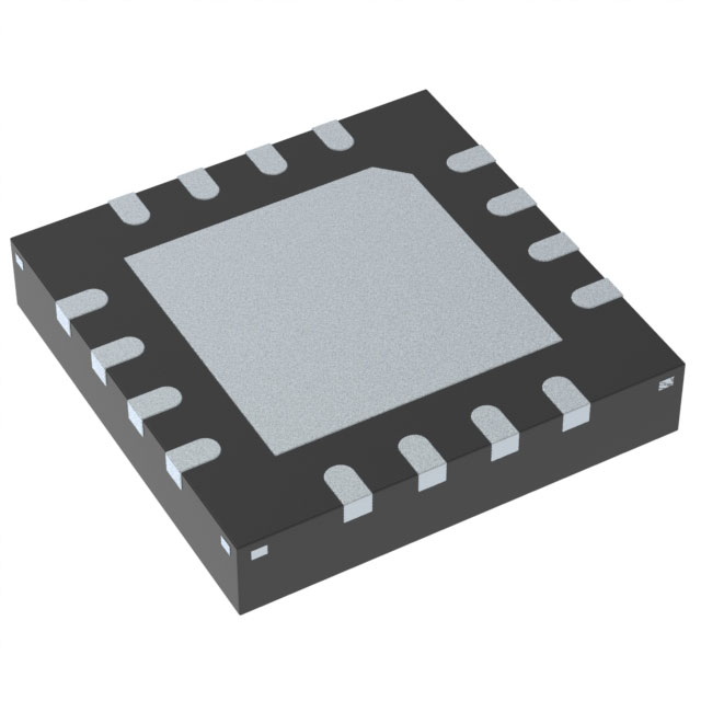
The TMUX7413FRRPR is a quad single-pole single-throw (SPST) analog switch from Texas Instruments, housed in a 16-pin WQFN package. It supports a single supply voltage range of 8 V to 44 V and dual supplies from ±5 V to ±22 V. The device features integrated fault protection capable of withstanding ±60 V overvoltage on source pins relative to ground, and up to ±85 V relative to the power supplies. It includes an active-low interrupt flag for fault status indication. Electrical characteristics include a typical on-resistance of 8.3 Ω, a maximum turn-on time of 930 ns, and a maximum turn-off time of 230 ns. The component operates within an ambient temperature range of -40°C to +125°C.
Verify the specific ordering suffix against the manufacturer's current orderable addendum to confirm the package type and tape-and-reel specifications. Ensure that the selected variant matches the required thermal performance and pin configuration for the target PCB layout. Cross-reference the datasheet revision history to confirm the document status is Production Data rather than Advanced Information or Preview.
Select the TMUX7413FRRPR when a break-before-make switching action is required among the TMUX741xF family. This specific model activates channels based on both high and low logic levels on the SEL pins. Verify that the application requires four independent SPST switches with fault protection. Confirm that the system can accommodate the 16-pin WQFN footprint and associated thermal dissipation requirements.
This component belongs to the TMUX741xF series of fault-protected analog switches. It shares the same core architecture and protection features as the TMUX7411F and TMUX7412F. The primary distinction lies in the logic control scheme; the TMUX7413F utilizes both high and low logic states for channel selection, whereas the other variants use only one polarity. All devices in this series offer identical electrical performance regarding resistance, leakage, and bandwidth.
The TMUX7411FRRPR and TMUX7412FRRPR are direct functional substitutes within the same package. They share identical pinouts and electrical ratings but differ in logic activation requirements. Ensure the control circuitry aligns with the specific logic state requirements of the replacement part.
When the source pin voltage exceeds the supply voltage by a threshold, the channel turns off automatically. The drain pin becomes floating during the fault, and the FF pin asserts low to indicate the error.
The FF pin is an open-drain output that provides an active-low interrupt flag. It signals when any of the source inputs experience an overvoltage fault condition.
Yes, the device offers powered-off protection. In the absence of power supplies, the channels remain in the OFF state regardless of the logic input conditions.
 TMUX7413FRRPR
The activity of extra discounts on wholesale prices is in full swing…
Please fill in your contact information and we will send you the latest wholesale price list.