 ChipApex | Global Electronic Components Supplier
SEARCH
Search Product
Search Post
— IC芯片 | 连接器 | 传感器 | 被动器件 —
Search productSearch post
— IC芯片 | 连接器 | 传感器 | 被动器件 —
Consult the customer manager about the wholesale price.
consultation hotline:86-132-6715-2157
email:[email protected]
Contact the product manager for consultation. One-stop consultation is available.
Do you want a lower wholesale price? Please send us your inquiry and we will reply immediately.
The TPS2413DR is a hot-swap controller designed for managing power insertion in backplane and peripheral applications. It integrates an N-channel MOSFET driver, current limit circuitry, and fault protection mechanisms. The device supports dual threshold current limiting with selectable hysteresis to prevent nuisance tripping during inrush events. It features adjustable soft-start timing via an external capacitor to control ramp-up speed. The controller monitors output voltage and current, providing active clamping during overcurrent conditions and disconnecting the load upon detecting faults such as overvoltage or short circuits.
Verify the complete orderable part number against the manufacturer's official database to ensure correct suffixes indicating package type and temperature range. Confirm that the DR suffix corresponds to the specified tape-and-reel packaging configuration required for automated assembly processes. Cross-reference the datasheet revision date to ensure compatibility with current design specifications and regulatory standards.
Evaluate the input voltage range and current handling capabilities against system requirements to ensure adequate headroom. Consider the external component selection for current limit thresholds and soft-start timing to meet specific inrush and fault response criteria. Assess thermal performance requirements based on expected load currents and ambient operating conditions to determine necessary heatsinking or PCB copper area.
This component belongs to Texas Instruments' family of hot-swap controllers, which are engineered for safe power insertion in modular electronic systems. These devices protect both the source and the load during connection events by managing inrush currents and isolating faults. The series typically includes variants with different voltage ratings and integration levels to suit diverse industrial and telecommunications power architectures.
Consult the official replacement matrix for direct pin-compatible alternatives within the same product family. Verify that any substitute device maintains identical electrical characteristics, particularly current limit thresholds and gate drive strength. Ensure that the alternative part supports the same package dimensions and thermal dissipation requirements to fit existing board layouts without modification.
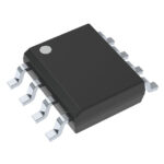 TPS2413DR
The activity of extra discounts on wholesale prices is in full swing…
Please fill in your contact information and we will send you the latest wholesale price list.





