 ChipApex | Global Electronic Components Supplier
SEARCH
Search Product
Search Post
— IC芯片 | 连接器 | 传感器 | 被动器件 —
Search productSearch post
— IC芯片 | 连接器 | 传感器 | 被动器件 —
Consult the customer manager about the wholesale price.
consultation hotline:86-132-6715-2157
email:[email protected]
Contact the product manager for consultation. One-stop consultation is available.
Do you want a lower wholesale price? Please send us your inquiry and we will reply immediately.
The TPW4051-SOBR is a single-pole octal-throw (SP8T) analog switch manufactured by 3PEAK, housed in a WSOP16 package. It supports supply voltages of 3.3 V, 5 V, 10 V, and ±5 V with an operating range of 3 V to 12 V. The device features a typical on-state resistance of 50 Ω at ±4.5 V or 9 V, 60 Ω at 4.5 V, and 300 Ω at 3 V. It offers a bandwidth of 200 MHz, turn-on time of 60 ns, and turn-off time of 50 ns. The component operates within a temperature range of –40°C to 125°C.
Verify the specific ordering suffix SOBR corresponds to the WSOP16 package type before procurement. Confirm that the required quantity aligns with the standard tape and reel packaging specifications provided in the official documentation. Ensure compatibility with RoHS standards and halogen-free requirements as defined by the manufacturer.
Select this component when an SP8T configuration is required for signal routing. Consider the on-resistance variations across different supply voltages and temperature ranges. Verify that the input voltage levels are compatible with the control logic and that the thermal characteristics of the WSOP16 package suit the application's power dissipation needs.
The TPW4051-SOBR belongs to the TPW4051 series of general-purpose analog switches from 3PEAK. This series includes variants with different package options such as SOP16, TSSOP16, and QFN3X3-16. The SOBR suffix specifically denotes the wide-body small-outline package variant, offering distinct physical dimensions compared to standard SOP packages while maintaining identical electrical performance.
Direct replacements include other TPW4051 variants with different packages, such as TPW4051-SR (SOP16), TPW4051-TR (TSSOP16), and TPW4051-QF4R (QFN3X3-16). These parts share identical electrical specifications but differ in physical footprint and thermal properties.
The E pin is the digital enable input. When held high, the switch is turned off regardless of the state of the select inputs S0, S1, and S2.
The device utilizes break-before-make switching action, which ensures that the previous channel is disconnected before the new channel is connected, preventing momentary shorting between outputs.
A 0.1-μF bypass capacitor is recommended between VCC and GND. If VEE is not connected to GND, another 0.1-μF bypass capacitor should be placed between VEE and GND to prevent power disturbance.
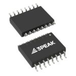 TPW4051-SOBR
The activity of extra discounts on wholesale prices is in full swing…
Please fill in your contact information and we will send you the latest wholesale price list.





