 ChipApex | Global Electronic Components Supplier
SEARCH
Search Product
Search Post
— IC芯片 | 连接器 | 传感器 | 被动器件 —
Search productSearch post
— IC芯片 | 连接器 | 传感器 | 被动器件 —
Consult the customer manager about the wholesale price.
consultation hotline:86-132-6715-2157
email:[email protected]
Contact the product manager for consultation. One-stop consultation is available.
Do you want a lower wholesale price? Please send us your inquiry and we will reply immediately.
The TS3004ITD1033T is a single-supply, second-generation oscillator/timer from Silicon Labs. It operates within a supply voltage range of 1.55V to 5.25V and consumes less than 2.4 μA (max) at 25kHz. The output period is user-adjustable from 3.3µs to 233s using a single external resistor on the RSET pin. It features separate FOUT and PWMOUT outputs with an output driver resistance of 160Ω. The device provides a period accuracy of 3% and drift of 0.02%/ºC. It is housed in a low-profile, 10-pin 3x3mm TDFN package with an exposed paddle.
Verify component authenticity through authorized channels. Confirm the specific ITD1033T suffix matches the required tape and reel packaging quantity of 3000 units. Ensure compatibility with the -40°C to +85°C operating temperature range for the intended application environment.
Select this component when ultra-low power consumption is critical compared to standard CMOS or 555-timer based solutions. Verify that the required output period falls within the 3.3µs to 233s range. Consider the 160Ω output drive capability and ensure load capacitance is minimized to maintain specified power levels.
The TS3004 belongs to the TS300x family of 'NanoWatt Analog' high-performance analog integrated circuits, alongside models like the TS3001, TS3002, TS3003, and TS3006. This family focuses on compact, easy-to-use timer solutions optimized for long-life, low-frequency applications.
Publicly confirmed substitute part numbers are not available in the provided documentation. Evaluate alternatives based on matching supply voltage ranges, output period capabilities, and package dimensions.
The output period is set by connecting a single external resistor to the RSET pin. For optimal performance, a resistor with 1% tolerance or lower is recommended.
The PWMOUT signal is anti-phase with respect to FOUT. A dead time of approximately 106ns exists between the falling edge of FOUT and the rising edge of PWMOUT.
The pulse width is primarily set by a capacitor connected to the CPWM pin. It can be further adjusted by applying a voltage between GND and VRSET to the PWM_CNTRL pin.
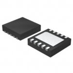 TS3004ITD1033T
The activity of extra discounts on wholesale prices is in full swing…
Please fill in your contact information and we will send you the latest wholesale price list.




