 ChipApex | Global Electronic Components Supplier
SEARCH
Search Product
Search Post
— IC芯片 | 连接器 | 传感器 | 被动器件 —
Search productSearch post
— IC芯片 | 连接器 | 传感器 | 被动器件 —
Consult the customer manager about the wholesale price.
consultation hotline:86-132-6715-2157
email:[email protected]
Contact the product manager for consultation. One-stop consultation is available.
Do you want a lower wholesale price? Please send us your inquiry and we will reply immediately.
The U6046B-MY is a bipolar long-term timer designed for automotive applications to limit high-load operation time. It features an RC oscillator where external components R2 and C2 determine timing characteristics, enabling delay times from 3.7 seconds to 20 hours. The device includes debounced ON, OFF, and TOGGLE inputs, a power-on reset function, and load-dump protection. It operates with a supply voltage between 6V and 16V via VBatt or at 5V. The relay control output provides up to 300 mA with an integrated Z-diode.
Verify the ordering suffix -MY corresponds to the DIP8 package when sourcing this component. Confirm that the specific revision matches the required design specifications, as datasheet revisions may update pinning or electrical characteristics. Ensure compatibility with the intended PCB footprint for the 8-pin dual in-line package.
Select external resistor R2 and capacitor C2 values based on the desired oscillator frequency using the provided dimensioning tables. For 12V systems, include the recommended R1 (510Ω) and C1 (47µF) filter circuit. For 5V supplies, connect Pin 7 to Pin 8 and omit the input filter components. Ensure the load current does not exceed the 300 mA output rating.
The U6046B series is a family of bipolar long-term timers originally manufactured by Atmel, which was later acquired by Microchip Technology. The U6046B-MY specifically denotes the lead-free version housed in an 8-pin DIP package. This component is part of a broader line of automotive analog circuits designed for robust performance in harsh electrical environments.
Public confirmed substitute part numbers are not available in the provided documentation. Verify pinout and electrical parameters against alternative long-term timers if cross-referencing other manufacturers' parts.
The delay time (td) depends on the oscillator frequency (f) and is calculated as td = 73728 / f. The frequency is determined by the external resistor R2 and capacitor C2 connected to Pin 6.
The TOGGLE input (Pin 5) allows the relay output to be activated or deactivated by pressing a switch. Each press changes the state of the relay output after the debounce time has elapsed.
Yes, it can operate at 5V. In this configuration, Pin 7 (VSTAB) must be connected to Pin 8 (VS), and the external R1C1 filter circuit should be omitted.


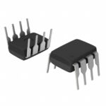 U6046B-MY
The activity of extra discounts on wholesale prices is in full swing…
Please fill in your contact information and we will send you the latest wholesale price list.



