 ChipApex | Global Electronic Components Supplier
SEARCH
Search Product
Search Post
— IC芯片 | 连接器 | 传感器 | 被动器件 —
Search productSearch post
— IC芯片 | 连接器 | 传感器 | 被动器件 —
Consult the customer manager about the wholesale price.
consultation hotline:86-132-6715-2157
email:[email protected]
Contact the product manager for consultation. One-stop consultation is available.
Do you want a lower wholesale price? Please send us your inquiry and we will reply immediately.
The Panasonic UP03390G0L is a composite transistor featuring an NPN Tr1 and PNP Tr2 in an SSMini5-F3 package. It operates with a maximum collector current of 100 mA and total power dissipation of 125 mW. The NPN element provides a transition frequency of 150 MHz, while the PNP element reaches 80 MHz. Both transistors support a 50 V collector-emitter voltage rating. Internal biasing includes R1 values of 47 kΩ for Tr1 and 10 kΩ for Tr2.
Verify the specific lifecycle status directly with Panasonic Industry before procurement, as this component may be classified under maintenance or discontinued stages. Confirm that the SSMini5-F3 package dimensions align with existing PCB footprints. Ensure compliance with RoHS Directive (EU 2002/95/EC) requirements for the target application environment.
Select this component when a matched NPN/PNP pair with integrated biasing is required for standard digital applications. The 100 mA current capability and 50 V breakdown voltage suit general-purpose switching tasks. Verify thermal management capabilities against the 125 mW total power dissipation limit at the intended operating temperature.
This part belongs to the UP03390 series of composite transistors manufactured by Panasonic Industry. It is designed specifically for digital circuits where space efficiency and simplified wiring are priorities. The device combines two epitaxial planar transistors within one encapsulation to streamline circuit layouts.
Consult official manufacturer resources for verified substitute part numbers. Cross-referencing should focus on matching the SSMini5-F3 package, 50 V ratings, and internal resistance configurations to ensure functional compatibility.
The NPN transistor (Tr1) has an input resistance (R1) of 47 kΩ, while the PNP transistor (Tr2) has an input resistance (R1) of 10 kΩ.
The transition frequency (fT) for the NPN element (Tr1) is 150 MHz under specified test conditions.
The SSMini5-F3 package contains five pins: Pin 1 is Emitter (Tr1), Pin 2 is Base (Tr1), Pin 3 is Emitter (Tr2), Pin 4 is Collector (Tr2), and Pin 5 is Collector (Tr1) / Base (Tr2).
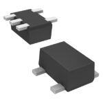 UP03390G0L
The activity of extra discounts on wholesale prices is in full swing…
Please fill in your contact information and we will send you the latest wholesale price list.




