ChipApex | Global Electronic Components Supplier
SEARCH
Search Product
Search Post
— IC芯片 | 连接器 | 传感器 | 被动器件 —
Search productSearch post
— IC芯片 | 连接器 | 传感器 | 被动器件 —
Consult the customer manager about the wholesale price.
consultation hotline:86-132-6715-2157
email:[email protected]
Contact the product manager for consultation. One-stop consultation is available.
Do you want a lower wholesale price? Please send us your inquiry and we will reply immediately.
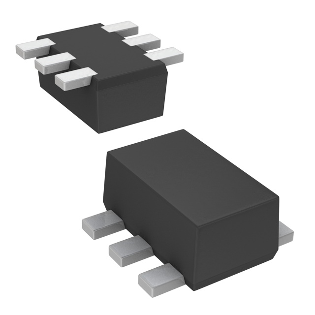
The UP04112G is a composite transistor device manufactured by Panasonic Electronic Components, designed for digital circuits. It integrates two PNP silicon epitaxial planar transistors into a single SSMini6-F2 package, each equipped with built-in bias resistors. The component supports a maximum collector current of -100 mA and withstands collector-emitter voltages up to -50 V. Key electrical characteristics include a minimum forward current transfer ratio (hFE) of 60 at -5 mA and a transition frequency of 80 MHz. The internal circuitry utilizes two 22 kΩ resistors per element, facilitating compact board layouts.
Verify the specific lifecycle status before procurement, as the datasheet indicates maintenance or discontinuation stages may apply. Confirm that the SSMini6-F2 package dimensions align with existing PCB footprints. Ensure design parameters remain within the absolute maximum ratings to prevent device failure during operation.
Select this component when space constraints require combining multiple discrete transistors and resistors into one footprint. The built-in 22 kΩ resistors simplify base drive calculations. Verify that the required switching speed does not exceed the 80 MHz transition frequency limit under the intended operating conditions.
This part belongs to the UP041xxG series of composite transistors from Panasonic. These devices are engineered to replace multiple discrete components, thereby reducing board space and simplifying assembly processes. The UP04112G specifically features PNP elements, distinguishing it from NPN variants within the same product family.
The datasheet identifies UNR2112 as the basic part number equivalent. Designers should verify pin compatibility and electrical specifications against other composite transistor models if sourcing alternatives.
Each transistor element contains two built-in resistors, R1 and R2, both with a nominal value of 22 kΩ.
The total power dissipation (PT) is rated at 125 mW at an ambient temperature of 25°C.
Pin 1 is Emitter (Tr1), Pin 2 is Base (Tr1), Pin 3 is Collector (Tr2), Pin 4 is Emitter (Tr2), Pin 5 is Base (Tr2), and Pin 6 is Collector (Tr1).
 UP04112G0L
The activity of extra discounts on wholesale prices is in full swing…
Please fill in your contact information and we will send you the latest wholesale price list.