ChipApex | Global Electronic Components Supplier
SEARCH
Search Product
Search Post
— IC芯片 | 连接器 | 传感器 | 被动器件 —
Search productSearch post
— IC芯片 | 连接器 | 传感器 | 被动器件 —
Consult the customer manager about the wholesale price.
consultation hotline:86-132-6715-2157
email:[email protected]
Contact the product manager for consultation. One-stop consultation is available.
Do you want a lower wholesale price? Please send us your inquiry and we will reply immediately.
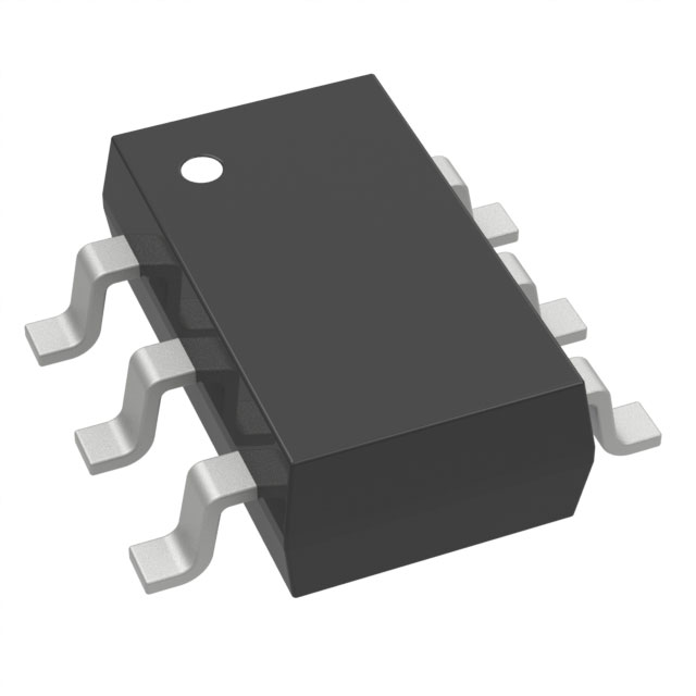
The Panasonic XN04322 is a composite transistor featuring an NPN epitaxial planar transistor (Tr1) and a PNP epitaxial planar transistor (Tr2) integrated into a single EIAJ SC-74 Mini6-G1 package. Designed for switching and digital circuits, the device incorporates built-in base resistors to reduce mounting area and assembly costs. The absolute maximum ratings specify a collector-emitter voltage of ±50 V, a collector current of ±500 mA, and a total power dissipation of 300 mW at 25°C ambient temperature. Electrical characteristics include a forward current transfer ratio (hFE) of 50 minimum, a collector-emitter saturation voltage of 0.25 V maximum, and a transition frequency of 200 MHz.
Verify component authenticity through authorized distribution channels or direct manufacturer confirmation. Review the latest product standards on the official Panasonic website to confirm current lifecycle status, as maintenance or discontinuation notices may apply. Ensure compliance with RoHS directives relevant to your specific manufacturing region before finalizing procurement orders.
Select this component when design constraints require dual complementary transistors with minimal footprint. Verify that the required collector current does not exceed 500 mA and that the operating voltage remains within the ±50 V limit. Confirm that the internal resistor values align with the driving requirements of the connected logic gates or control signals.
This part replaces discrete combinations such as the UNR2222 paired with the UNR2122. It consolidates two separate components into a single surface-mount unit, facilitating automated placement and reducing overall bill-of-materials complexity for standard electronic equipment designs.
Direct substitutes include the UNR2222 combined with the UNR2122 discrete pair. Verify pinout compatibility and electrical parameters against the original design specifications before implementing any alternative component in the circuit layout.
Pin 1 is the Collector for Tr1, Pin 2 is the Base for Tr2, Pin 3 is the Emitter for Tr2, Pin 4 is the Collector for Tr2, Pin 5 is the Base for Tr1, and Pin 6 is the Emitter for Tr1.
The nominal input resistance is 4.7 kΩ, with a tolerance range specified from -30% to +30%.
No. The datasheet specifies use for standard applications only and explicitly advises consulting sales staff for special applications like aerospace due to reliability requirements.
 XN0432200L
The activity of extra discounts on wholesale prices is in full swing…
Please fill in your contact information and we will send you the latest wholesale price list.