 ChipApex | Global Electronic Components Supplier
SEARCH
Search Product
Search Post
— IC芯片 | 连接器 | 传感器 | 被动器件 —
Search productSearch post
— IC芯片 | 连接器 | 传感器 | 被动器件 —
Consult the customer manager about the wholesale price.
consultation hotline:86-132-6715-2157
email:[email protected]
Contact the product manager for consultation. One-stop consultation is available.
Do you want a lower wholesale price? Please send us your inquiry and we will reply immediately.
The UMW 12N10 is an N-Channel MOSFET with a 100 V drain-source voltage rating. It features a maximum continuous drain current of 13 A at a case temperature of 25 °C and a pulsed drain current capability of 40 A. The device exhibits a typical on-state resistance of 120 mΩ at VGS = 10 V and ID = 3 A. Total gate charge is typically 24 nC under standard test conditions. Thermal performance includes a junction-to-case thermal resistance of 0.85 °C/W (typical) and a maximum power dissipation of 96 W at TC = 25 °C.
Verify the specific package variant, as the datasheet indicates TO-252 mechanical data. Confirm that the ordering code matches the required tape and reel quantity of 2500 units. Ensure the component meets RoHS compliance standards if required by the manufacturing process. Cross-reference the manufacturer's latest revision notes for any updates to electrical limits or thermal ratings before finalizing the bill of materials.
Select this component when a 100 V breakdown voltage and moderate current handling are required. Evaluate the thermal management strategy carefully, as power dissipation drops significantly from 96 W at 25 °C case temperature to 3 W at 25 °C ambient temperature. Consider the gate charge requirements against the driving capability of the control IC to ensure adequate switching speeds without excessive drive losses.
This part belongs to the UMW discrete semiconductor portfolio, specifically within the N-Channel MOSFET category. It is designed for general-purpose power switching applications requiring low on-resistance and reliable thermal performance. The device utilizes a surface-mount package suitable for automated assembly processes in consumer electronics and industrial power supplies.
Check for direct pin-compatible alternatives with matching VDS and RDS(on) specifications. Verify that substitute components offer equivalent or superior avalanche energy ratings and thermal resistance values to maintain system safety margins.
The continuous drain current decreases to 13 A when the case temperature is maintained at 125 °C.
The on-state resistance increases positively with junction temperature, rising significantly at 125 °C and 175 °C compared to the 25 °C baseline.
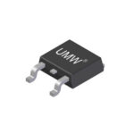 12N10
12N10
The activity of extra discounts on wholesale prices is in full swing…
Please fill in your contact information and we will send you the latest wholesale price list.





