 ChipApex | Global Electronic Components Supplier
SEARCH
Search Product
Search Post
— IC芯片 | 连接器 | 传感器 | 被动器件 —
Search productSearch post
— IC芯片 | 连接器 | 传感器 | 被动器件 —
Consult the customer manager about the wholesale price.
consultation hotline:86-132-6715-2157
email:[email protected]
Contact the product manager for consultation. One-stop consultation is available.
Do you want a lower wholesale price? Please send us your inquiry and we will reply immediately.
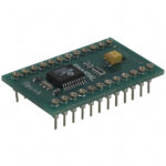
The Parallax PWMPAL (#28020) is a peripheral module designed to expand the capabilities of 24-pin BASIC Stamp microcontrollers. It provides up to four independent PWM output channels and four 16-bit hardware counters. Communication with the host microcontroller occurs via a serial link on pin P0 using the Parallax AppMod protocol at baud rates of 9600, 19,200, or 38,400. The module generates TTL-level square waves with frequencies ranging from 0.3 Hz to 20 kHz. Timing parameters are defined by 16-bit values in 25-microsecond increments, allowing precise control over frequency and duty cycle.
Verify the package type and pin configuration against the 24-pin BASIC Stamp socket requirements. Confirm that the specific revision matches the documentation dated 02/2005. Ensure the serial interface voltage levels are compatible with the host microcontroller's logic family before integration.
Select this component when additional PWM channels or hardware counters are required for 24-pin BASIC Stamp modules. It is suitable for applications needing independent timing control without consuming microcontroller processing cycles. Verify that the host program reserves pin P0 for serial communication and manages potential conflicts on pins P12–P15.
The PWMPAL functions as a smart socket that mounts directly beneath the BASIC Stamp microcontroller. It utilizes a small coprocessor to handle PWM generation and counting tasks independently. This architecture allows the main microcontroller to perform other operations while the PWMPAL maintains accurate waveforms and counts events in the background.
This is a specialized peripheral for the BASIC Stamp ecosystem. Direct functional replacements are limited to other Parallax expansion modules or custom FPGA/CPLD solutions implementing the same serial protocol and pin mapping.
Frequency is determined by the sum of the on-time and off-time values multiplied by 25 microseconds. The formula is Frequency = 1 / ((OnTime + OffTime) * 0.000025).
Yes, each channel can be set to hardware control mode. In this mode, the corresponding counter input pin (P8–P11) must be high for the PWM output to be active.
Conflicts may occur. The documentation advises setting the associated host pins to input mode when PWMPAL motor control outputs are enabled to prevent damage or unpredictable results.



 28020
28020
The activity of extra discounts on wholesale prices is in full swing…
Please fill in your contact information and we will send you the latest wholesale price list.



