 ChipApex | Global Electronic Components Supplier

SEARCH
Search Product
Search Post
— IC芯片 | 连接器 | 传感器 | 被动器件 —
Search productSearch post
— IC芯片 | 连接器 | 传感器 | 被动器件 —
Consult the customer manager about the wholesale price.
consultation hotline:86-132-6715-2157
email:[email protected]
Contact the product manager for consultation. One-stop consultation is available.
Do you want a lower wholesale price? Please send us your inquiry and we will reply immediately.
74AHC1G4214GW-Q10H is listed in the Counter Dividers range at ChipApex. The manufacturer field lists Nexperia USA Inc.. Its product description is IC DIVIDER BY 2 14-BIT 5TSSOP. Review the specifications below when checking this part for your BOM.
The Nexperia 74AHC1G4214GW-Q10H is a single-channel, 14-stage frequency divider and oscillator integrated circuit. It comprises a chain of 14 flip-flops that divide the input frequency by 16384 (2^14). The device operates on negative-going transitions at the X1 clock input. Pin X2 serves as an oscillator output or can be left floating when used as a buffer. The component supports a supply voltage range from 2.0 V to 5.5 V and functions within ambient temperatures of -40 °C to +125 °C. It utilizes a TSSOP5 plastic thin shrink small outline package.
Verify the specific suffix 'Q10H' against official Nexperia documentation to confirm exact marking codes and package variations. Ensure compatibility with AEC-Q100 Grade 1 requirements if deploying in automotive contexts. Cross-reference the ordering information table for precise temperature ranges and package dimensions before finalizing procurement specifications.
Select this component when a single-chip solution for dividing frequencies by 16384 is required. It is appropriate for designs needing overvoltage tolerance up to 5.5 V on inputs while operating at lower supply voltages. Consider its automotive qualification status if the application demands compliance with strict industry reliability standards.
This part belongs to the 74AHC1G4214-Q100 family of 14-stage dividers. It shares functional similarities with other single-gate logic devices but is distinct due to its internal counter chain architecture. The product line emphasizes compact packaging and robust performance across wide temperature ranges for industrial and automotive sectors.
Direct substitutes include other 14-stage dividers from the same manufacturer series. Verify pinout compatibility and electrical parameters such as propagation delay and supply voltage limits before swapping components in existing designs.
The X1 and X2 pins form an inverting stage that can drive an external crystal. A bias resistor and limiting resistor are typically connected between these pins to establish oscillation conditions.
When the device is used strictly as a frequency divider buffer rather than an oscillator, the X2 pin should be left floating to prevent interference with the counting chain.
Explore related parts through Logic, Integrated Circuits (ICs), all product categories, ChipApex homepage.
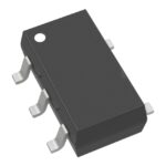 74AHC1G4214GW-Q10H

The activity of extra discounts on wholesale prices is in full swing…
Please fill in your contact information and we will send you the latest wholesale price list.




