 ChipApex | Global Electronic Components Supplier
SEARCH
Search Product
Search Post
— IC芯片 | 连接器 | 传感器 | 被动器件 —
Search productSearch post
— IC芯片 | 连接器 | 传感器 | 被动器件 —
Consult the customer manager about the wholesale price.
consultation hotline:86-132-6715-2157
email:[email protected]
Contact the product manager for consultation. One-stop consultation is available.
Do you want a lower wholesale price? Please send us your inquiry and we will reply immediately.
The AS2540 is a CMOS integrated circuit designed for remote-controlled single-chip telephones. It integrates a speech circuit with line adaptation, 2/4-wire conversion, and separate receive/transmit amplifiers. The device includes an MF dialler, ring frequency detector, and tone ringer. It operates in mainpower mode under CPU control or backup mode as an independent dialler during power failure. Powered by the A/B telephone line, it features a two-wire serial interface (UART 9600 baud, 8N1) for communication with a host processor. The IC supports soft clipping, line loss compensation, and complex impedance programming via external components.
Verify component authenticity through authorized channels due to end-of-life status. Confirm package suffix T for SOIC-28 or Q for Dice-on-Foil availability. Check current distributor stock levels as manufacturing has ceased. Ensure compatibility with existing PCB layouts and serial interface protocols before procurement.
Select based on required operating mode; mainpower mode requires CPU reset of the watchdog timer, while backup mode allows independent dialling. Verify supply voltage range of 3.6V to 5V and operating temperature of -15°C to +60°C. Consider external components for AC impedance and side tone adaptation. Ensure UART interface matches 9600 baud, 8N1 configuration.
The AS2540 belongs to the family of single-chip telephone interface solutions from ams OSRAM (formerly austriamicrosystems). It replaces discrete designs by integrating line interface, speech processing, and dialling functions into one CMOS chip. The device is designed for cost-effective integration in analogue telephone systems requiring reliable operation under varying line conditions.
Public confirmed substitute part numbers are not available in the provided documentation. The AS2540 is listed as discontinued. Designers should evaluate legacy stock or consult manufacturer archives for potential obsolescence management strategies.
In backup mode, the AS2540 operates independently using line current. It activates the keyscan and handset path, allowing it to function as a basic MF dialler for digits 0-9*# without CPU intervention.
The MODE pin selects the DTMF output level and Line Loss Compensation (LLC) range. Its connection to the keyboard matrix determines settings such as -4/-6dBm, -6/-8dBm, or -8/-10dBm levels and LLC ranges of 45mA-75mA or 20mA-50mA.
The AS2540 requires a 3.58MHz ceramic resonator connected to the OSC pin. The recommended type is Murata CSA 3.58MG312AM or a compatible equivalent.
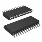 AS2540
The activity of extra discounts on wholesale prices is in full swing…
Please fill in your contact information and we will send you the latest wholesale price list.






