 ChipApex | Global Electronic Components Supplier
SEARCH
Search Product
Search Post
— IC芯片 | 连接器 | 传感器 | 被动器件 —
Search productSearch post
— IC芯片 | 连接器 | 传感器 | 被动器件 —
Consult the customer manager about the wholesale price.
consultation hotline:86-132-6715-2157
email:[email protected]
Contact the product manager for consultation. One-stop consultation is available.
Do you want a lower wholesale price? Please send us your inquiry and we will reply immediately.
The AT17LV010-10PU is a 1-Mbit (1,048,576 x 1-bit) serial EEPROM designed for FPGA configuration. It operates within a supply voltage range of 3.0V to 5.5V and supports maximum clock frequencies up to 10 MHz at 3.3V and 12.5 MHz at 5.0V. The device utilizes an 8-lead PDIP package and features industrial temperature ratings from -40°C to +85°C. Key electrical characteristics include active mode current consumption of 5 mA at 3.3V and standby current of 100 µA.
Verify the specific ordering code suffix against the manufacturer's official documentation to ensure correct package type and voltage compatibility. Confirm that the component meets the required industrial temperature range specifications for your application environment. Cross-reference the datasheet revision history to ensure no design changes affect pinout or functionality.
Select this component when a 1-Mbit capacity is required for SRAM-based FPGA configuration. Ensure the target FPGA supports Master Serial Mode for direct interfacing without external controllers. Verify that the system power supply remains within the specified 3.0V to 5.5V range to maintain reliable operation and data retention.
This part belongs to the AT17LV series of FPGA Configuration EEPROMs manufactured by Microchip Technology (formerly Atmel). These configurators are specifically engineered to provide cost-effective and easy-to-use memory solutions for loading configuration programs into various FPGA families. The series includes densities ranging from 65 Kbit to 4 Mbit.
AT17LV010-10CU
The CEO output goes Low when the address counter reaches its maximum value. In a daisy chain, this signal drives the CE input of the next configurator, enabling its data output after the previous device finishes reading.
The READY pin is an open-collector indicator driven Low during the power-up reset cycle. It is released (tri-stated) when the power-up reset is complete, signaling that the device is ready for operation.
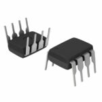 AT17LV010-10PU
The activity of extra discounts on wholesale prices is in full swing…
Please fill in your contact information and we will send you the latest wholesale price list.





