 ChipApex | Global Electronic Components Supplier
SEARCH
Search Product
Search Post
— IC芯片 | 连接器 | 传感器 | 被动器件 —
Search productSearch post
— IC芯片 | 连接器 | 传感器 | 被动器件 —
Consult the customer manager about the wholesale price.
consultation hotline:86-132-6715-2157
email:[email protected]
Contact the product manager for consultation. One-stop consultation is available.
Do you want a lower wholesale price? Please send us your inquiry and we will reply immediately.
The BA12004BF-E2 is a monolithic integrated circuit comprising seven Darlington transistor circuits. It features built-in base current-limiting resistors and output surge-absorbing clamp diodes. The device supports an operating supply voltage range from -0.5 V to +30 V, with a maximum output breakdown voltage of 60 V. Each channel provides a maximum DC output current of 500 mA and a minimum DC current gain of 1000. The input resistor for the BA12004 series is specified at 10.5 kΩ. The component operates within a temperature range of -40°C to +85°C and is available in SOP16 packaging.
Verify the specific ordering suffix E2 corresponds to the embossed tape and reel packaging format for the SOP16 variant. Confirm that the component status is acceptable for the intended design, as the datasheet indicates this series is not recommended for new designs. Ensure compatibility with existing PCB footprints and reflow soldering profiles for surface-mount assembly.
Select the BA12004BF-E2 when seven low-side switching channels are required with high current gain capabilities. The 10.5 kΩ internal input resistor distinguishes this model from the BA12003 series, affecting drive current requirements. Verify thermal dissipation limits based on ambient temperature and copper area, as power derating curves are provided for the SOP16 package configuration.
This component belongs to the BA1200xB family of high-voltage, high-current Darlington transistor arrays manufactured by ROHM Semiconductor. The BA12004BF-E2 specifically denotes the SOP16 surface-mount package variant with tape-and-reel packaging. It shares architectural similarities with the DIP16 through-hole versions but differs in physical dimensions and thermal characteristics.
Direct substitutes include BA12003BF-E2, which shares the same package and pinout but utilizes a 2.7 kΩ input resistor instead of 10.5 kΩ. Other family members such as BA12004B (DIP16) offer identical electrical performance in a different package style. Cross-model substitution requires verification of input drive voltage levels relative to the internal resistor values.
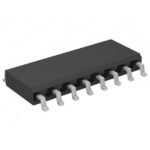 BA12004BF-E2
The activity of extra discounts on wholesale prices is in full swing…
Please fill in your contact information and we will send you the latest wholesale price list.





