 ChipApex | Global Electronic Components Supplier
SEARCH
Search Product
Search Post
— IC芯片 | 连接器 | 传感器 | 被动器件 —
Search productSearch post
— IC芯片 | 连接器 | 传感器 | 被动器件 —
Consult the customer manager about the wholesale price.
consultation hotline:86-132-6715-2157
email:[email protected]
Contact the product manager for consultation. One-stop consultation is available.
Do you want a lower wholesale price? Please send us your inquiry and we will reply immediately.
The BA1604F-E2 is a PLL tone decoder IC from ROHM Semiconductor, designed for precise frequency selection. It integrates a PLL circuit, detection circuit, voltage comparator, and output logic drive. The center frequency (f0) is set by external CR components on Pins 5 and 6, with a tuning range of 20:1 using an external resistor. The device supports a supply voltage up to 20V and can drive loads up to 100mA. Key electrical parameters include a detection bandwidth adjustable between 0% and 14%, high out-of-band noise rejection, and stable center frequency operation.
Verify the specific suffix E2 against the manufacturer's current lifecycle status, as documentation indicates potential end-of-life or non-recommended-for-new-design classifications for related variants. Confirm RoHS compliance and package availability through authorized distributors. Ensure the ordering code matches the exact pinout and electrical specifications required for the target application design.
Select this component when a dedicated PLL-based tone decoder is required for communication interfaces. The 20:1 frequency tuning range allows flexibility in system design without changing the core IC. Consider the 100mA output drive capability for direct load interfacing. Verify that the external CR component tolerances align with the required frequency stability and bandwidth specifications for the intended environment.
The BA1604 series belongs to ROHM's Communication ICs portfolio, specifically categorized as PLL tone decoders. This family provides solutions for frequency detection and decoding tasks in analog and digital hybrid circuits. The BA1604F variant typically denotes a specific package configuration within the standard BA1604 functional line, maintaining compatibility with industry-standard tone decoding applications.
The datasheet explicitly notes compatibility with EXAR XR-567 and Signetics NE567. These parts serve as direct functional substitutes in existing designs. Verify pin-to-pin compatibility and electrical parameter margins before substitution to ensure system performance remains within acceptable limits.
The center frequency (f0) is set by the resistor R1 connected between Pins 5 and 6 and the capacitor C1 connected between Pin 6 and ground.
The output circuit can withstand and drive a load current of up to 100mA.
The detection bandwidth is varied independently between 0% and 14% by adjusting the loop filter capacitor C2 connected between Pin 2 and ground.
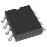 BA1604F-E2
The activity of extra discounts on wholesale prices is in full swing…
Please fill in your contact information and we will send you the latest wholesale price list.





