 ChipApex | Global Electronic Components Supplier

SEARCH
Search Product
Search Post
— IC芯片 | 连接器 | 传感器 | 被动器件 —
Search productSearch post
— IC芯片 | 连接器 | 传感器 | 被动器件 —
Consult the customer manager about the wholesale price.
consultation hotline:86-132-6715-2157
email:[email protected]
Contact the product manager for consultation. One-stop consultation is available.
Do you want a lower wholesale price? Please send us your inquiry and we will reply immediately.
CD40106BCN is listed in the Inverter Gates range at ChipApex. The manufacturer field lists onsemi. Its product description is IC INVERT SCHMITT 6CH 1IN 14MDIP. Review the specifications below when checking this part for your BOM.
The CD40106BCN is a monolithic CMOS Hex Schmitt Trigger integrated circuit manufactured by Fairchild Semiconductor. It contains six independent inverters with Schmitt-trigger inputs, constructed using N and P-channel enhancement transistors. The device operates within a DC supply voltage range of 3V to 15V and supports an operating temperature range of -55°C to +125°C. Key electrical characteristics include a typical propagation delay of 400ns at 5V and guaranteed hysteresis of at least 0.2 VDD. It is housed in a 14-lead Plastic Dual-In-Line (PDIP) package.
Verify the specific manufacturer origin, as this component was originally produced by Fairchild Semiconductor. Confirm package integrity for the 14-lead PDIP configuration. Ensure the revision date aligns with project requirements, noting the datasheet was revised in September 2003. Check for RoHS compliance status if required by current manufacturing standards.
Select this component when hex inverter functionality with built-in hysteresis is required. It serves as a direct equivalent to the MM74C14. Consider the 14-lead PDIP package for through-hole mounting needs. Verify that the 3V to 15V supply range matches the system power architecture before finalizing the design.
This part belongs to the 4000 series of CMOS logic devices. It functions specifically as a hex inverter with Schmitt triggers. The 'N' suffix denotes the 14-lead Plastic Dual-In-Line package. It is distinct from standard inverters due to its hysteresis properties, which improve noise tolerance in digital signal processing tasks.
The MM74C14 is documented as an equivalent part number. Other manufacturers may produce compatible hex Schmitt trigger inverters within the 4000 series family. Verify pinout and electrical specifications before substituting with generic equivalents.
The datasheet guarantees a hysteresis voltage (VT+ − VT−) of at least 0.2 VDD.
All inputs are protected from static discharge damage by diode clamps connected to VDD and VSS.
Explore related parts through Logic, Integrated Circuits (ICs), all product categories, ChipApex homepage.
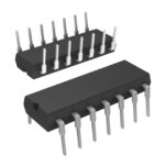 CD40106BCN

The activity of extra discounts on wholesale prices is in full swing…
Please fill in your contact information and we will send you the latest wholesale price list.





