 ChipApex | Global Electronic Components Supplier
SEARCH
Search Product
Search Post
— IC芯片 | 连接器 | 传感器 | 被动器件 —
Search productSearch post
— IC芯片 | 连接器 | 传感器 | 被动器件 —
Consult the customer manager about the wholesale price.
consultation hotline:86-132-6715-2157
email:[email protected]
Contact the product manager for consultation. One-stop consultation is available.
Do you want a lower wholesale price? Please send us your inquiry and we will reply immediately.
The DDTD113EU-7-F is an NPN pre-biased transistor manufactured by Diodes Incorporated, housed in a SOT323 surface-mount package. It features built-in biasing resistors with nominal values of R1 = 1kΩ and R2 = 10kΩ. The device supports a supply voltage (VCC) up to 50V and a continuous collector current of 500mA. Electrical characteristics include a minimum DC current gain (hFE) of 33 at 50mA and a typical gain-bandwidth product of 200MHz. Thermal performance specifies a power dissipation of 250mW and a junction-to-ambient thermal resistance of 500°C/W. Operating and storage temperatures range from -55°C to +150°C.
Verify component status before design finalization as this part number is listed as obsolete in official documentation. Confirm availability through authorized distributors or secondary markets if immediate procurement is required. Ensure that any replacement components maintain identical pinout compatibility and electrical specifications to prevent circuit redesign. Validate RoHS compliance requirements against local regulatory standards prior to ordering.
Select this component when a compact NPN solution with integrated base and emitter resistors is required. The 1kΩ base resistor suits moderate drive currents, while the 10kΩ emitter resistor provides stability. Consider the 500mA current limit and 50V voltage rating against load requirements. Evaluate thermal constraints given the 250mW dissipation limit in small packages. Verify AEC-Q101 qualification needs for automotive environments.
This component belongs to the DDTD(XXXX)U series of NPN pre-biased transistors. It shares the same SOT323 footprint and epitaxial construction as other variants like the DDTD113ZU-7-F. Differences primarily involve internal resistor ratios and specific marking codes. The series offers complementary PNP types within the DDTA family for push-pull applications.
Direct substitutes include the DDTD113ZU-7-F, which maintains identical resistor values but may differ in marking. Verify equivalent electrical parameters such as VCEO, IC, and hFE. Check package dimensions and pin assignments to ensure mechanical compatibility without PCB layout modifications.
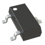 DDTD113EU-7-F
The activity of extra discounts on wholesale prices is in full swing…
Please fill in your contact information and we will send you the latest wholesale price list.





