 ChipApex | Global Electronic Components Supplier

SEARCH
Search Product
Search Post
— IC芯片 | 连接器 | 传感器 | 被动器件 —
Search productSearch post
— IC芯片 | 连接器 | 传感器 | 被动器件 —
Consult the customer manager about the wholesale price.
consultation hotline:86-132-6715-2157
email:[email protected]
Contact the product manager for consultation. One-stop consultation is available.
Do you want a lower wholesale price? Please send us your inquiry and we will reply immediately.
DSTF2060C is listed in the Diode Arrays range at ChipApex. The manufacturer field lists Littelfuse Inc.. Its product description is DIODE ARR SCHOT 60V 10A ITO220AB. Review the specifications below when checking this part for your BOM.
The Littelfuse DSTF2060C is a Schottky Barrier Rectifier featuring a dual common cathode configuration in an ITO-220AB package. It provides a total average forward current of 20 A (10 A per leg) and a peak inverse voltage of 60 V. The device supports a peak one-cycle non-repetitive surge current of 150 A per leg. Electrical characteristics include a maximum forward voltage drop of 0.65 V at 10 A and 25 °C, and a maximum reverse current of 40 mA at 125 °C. Thermal resistance from junction to case is 6.0 °C/W per leg, with an operating junction temperature range of -55 °C to +150 °C.
Verify the specific ordering suffix against official Littelfuse documentation to confirm exact packaging and marking details. Confirm that the component meets required RoHS compliance standards for your target market. Ensure thermal management designs account for the specified junction-to-case thermal resistance values under actual load conditions.
Select this component for applications requiring low forward voltage drops and high-frequency switching performance. The common cathode layout simplifies circuit design for dual-leg rectification needs. Verify that the 60 V rating aligns with system voltage peaks and that the 20 A total current capacity suits the continuous load requirements.
The DSTF2060C belongs to the Littelfuse DST series of ultra-low VF Schottky Barrier Rectifiers. This series is engineered to meet commercial and industrial application requirements by offering high temperature stability, low leakage currents, and reduced forward voltage drops compared to standard rectifiers.
Consult official Littelfuse cross-reference guides for verified substitutes. Ensure any replacement maintains the same ITO-220AB footprint, common cathode configuration, and equivalent electrical ratings for voltage and current handling.
The RSM isolation voltage depends on mounting: 4500 V for clip mounting with epoxy body away from heatsink edge, 3500 V if inside the heatsink, and 1500 V for screw mounting.
Reverse current increases significantly with temperature; it is rated at a maximum of 0.85 mA at 25 °C and rises to 40 mA at 125 °C.
The typical junction capacitance per leg is 628 pF, measured at VR = 5V, TC = 25 °C, and fSIG = 1MHz.
Explore related parts through Rectifiers, Diodes, Discrete Semiconductor Products, all product categories.
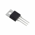 DSTF2060C

The activity of extra discounts on wholesale prices is in full swing…
Please fill in your contact information and we will send you the latest wholesale price list.





