 ChipApex | Global Electronic Components Supplier
SEARCH
Search Product
Search Post
— IC芯片 | 连接器 | 传感器 | 被动器件 —
Search productSearch post
— IC芯片 | 连接器 | 传感器 | 被动器件 —
Consult the customer manager about the wholesale price.
consultation hotline:86-132-6715-2157
email:[email protected]
Contact the product manager for consultation. One-stop consultation is available.
Do you want a lower wholesale price? Please send us your inquiry and we will reply immediately.
The DTC115EET1 is an NPN silicon Bias Resistor Transistor (BRT) from onsemi, integrating a single transistor with a monolithic bias network consisting of two resistors: a series base resistor and a base-emitter resistor. This integration replaces individual discrete components to reduce system cost and board space. The device is housed in the SC-75/SOT-416 package designed for low power surface mount applications. Key electrical parameters include a collector-emitter voltage (VCEO) of 50 Vdc, a collector current (IC) of 100 mAdc, and total device dissipation of 200 mW on an FR-4 board at minimum pad size. The internal resistors R1 and R2 are both 100 kOhms.
Verify the specific ordering suffix when sourcing this component. The standard part number DTC115EET1 may be supplied in lead-free packaging designated by the suffix 'G' (DTC115EET1G). Confirm the exact marking code '8N' and shipping configuration, typically provided in 3000-unit tape and reel quantities, matches the requirements of the procurement specification before finalizing orders.
Select this component when a compact solution is required to replace a discrete transistor and its associated bias resistors. Ensure the application operates within the 50 Vdc collector-emitter voltage limit and 100 mA collector current rating. Verify that the 100 kOhm internal resistor values provide appropriate biasing for the intended logic interface or switching load without exceeding the thermal dissipation limits of the SOT-416 package.
This device belongs to the DTC114EET1 Series, which includes various NPN BRTs with different internal resistor combinations. It shares the same SC-75/SOT-416 physical footprint and pinout as other members of this family, such as the DTC114EET1 and DTC124EET1, allowing for potential mechanical compatibility while differing in electrical characteristics due to varying internal resistance ratios.
Direct replacements within the same series include the DTC115EET1G, which denotes the lead-free variant. Cross-manufacturer equivalents should be verified against the specific 100 kOhm/100 kOhm resistor ratio and the 50 V/100 mA ratings to ensure functional parity in existing designs.
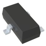 DTC115EET1
The activity of extra discounts on wholesale prices is in full swing…
Please fill in your contact information and we will send you the latest wholesale price list.





