 ChipApex | Global Electronic Components Supplier

SEARCH
Search Product
Search Post
— IC芯片 | 连接器 | 传感器 | 被动器件 —
Search productSearch post
— IC芯片 | 连接器 | 传感器 | 被动器件 —
Consult the customer manager about the wholesale price.
consultation hotline:86-132-6715-2157
email:[email protected]
Contact the product manager for consultation. One-stop consultation is available.
Do you want a lower wholesale price? Please send us your inquiry and we will reply immediately.
The GSIB660-E3/45 is a single-phase bridge rectifier from Vishay General Semiconductor, utilizing the GSIB-5S through-hole package. It features a maximum repetitive peak reverse voltage (VRRM) of 600 V and supports a maximum average forward rectified output current (IF(AV)) of 6.0 A at a case temperature of 100 °C. The device exhibits a maximum instantaneous forward voltage drop (VF) of 0.95 V at an IF of 3.0 A, with a peak forward surge current (IFSM) rating of 180 A. Operating junction and storage temperatures range from -55 °C to +150 °C.
Verify component authenticity by cross-referencing the manufacturer's document number 88648 and revision date against official Vishay channels. Confirm compliance with RoHS directives and JESD 201 class 1A whisker test requirements via the provided material categorization documentation. Ensure ordering suffixes match the specified tube packaging format.
Select this component when a 600 V blocking capability and 6.0 A continuous current are required within a thin single-in-line form factor. Evaluate thermal management needs based on the specified thermal resistance values for heatsink or PCB mounting configurations. Verify that the operating environment remains within the -55 °C to +150 °C junction temperature limits.
This part belongs to the GSIB6xx series of single-phase bridge rectifiers manufactured by Vishay General Semiconductor. The series includes variants with different voltage ratings such as GSIB620, GSIB640, and GSIB680, all sharing the same GSIB-5S package style and general electrical characteristics except for their specific reverse voltage capabilities.
Direct substitutes within the same family include GSIB640-E3/45 and GSIB680-E3/45, which share identical packages but differ in voltage ratings. Cross-family replacements must be evaluated for matching current, voltage, and thermal specifications.
The maximum non-repetitive peak forward surge current (IFSM) is 180 A, measured using the JEDEC method with a single sine-wave superimposed on rated load.
The typical forward voltage drop decreases as the junction temperature increases, as illustrated in the typical forward characteristics curve for junction temperatures ranging from 25 °C to 150 °C.
The recommended mounting torque is 5.7 cm-kg (5 inches-lbs), while the maximum allowable mounting torque is 10 cm-kg (8.8 inches-lbs).
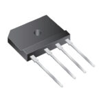 GSIB660-E3/45

The activity of extra discounts on wholesale prices is in full swing…
Please fill in your contact information and we will send you the latest wholesale price list.





