 ChipApex | Global Electronic Components Supplier

SEARCH
Search Product
Search Post
— IC芯片 | 连接器 | 传感器 | 被动器件 —
Search productSearch post
— IC芯片 | 连接器 | 传感器 | 被动器件 —
Consult the customer manager about the wholesale price.
consultation hotline:86-132-6715-2157
email:[email protected]
Contact the product manager for consultation. One-stop consultation is available.
Do you want a lower wholesale price? Please send us your inquiry and we will reply immediately.
HSMP-4890-TR2G is listed in the RF Diode range at ChipApex. The manufacturer field lists Broadcom Limited. Its product description is RF DIODE PIN 100V SOT-23-3. Review the specifications below when checking this part for your BOM.
The HSMP-4890-TR2G is a surface mount RF PIN switch diode from the HSMP-489x series, manufactured by Broadcom Limited. It features an ultra-low parasitic inductance design optimized for high-frequency applications ranging from 500 MHz to 3 GHz. The device utilizes a Dual Anode configuration housed in an SOT-363 package. Key electrical specifications include a breakdown voltage (VBR) of 100 V, a maximum series resistance (RS) of 2.5 Ω at 5 mA forward current, and a total capacitance (CT) of 0.375 pF measured at 1 MHz. The component supports a peak inverse voltage of 100 V and operates within a junction temperature range of -65°C to +150°C.
Verify component authenticity through authorized distributors or direct manufacturer channels. Confirm RoHS compliance status and check for End-of-Life notifications or Product Change Notices prior to procurement. Ensure storage conditions adhere to moisture sensitivity levels specified in the datasheet to prevent damage during assembly.
Select this component when ultra-low inductance is critical for performance above 500 MHz. The Dual Anode configuration suits designs requiring specific biasing arrangements. Compare series resistance and capacitance values against system requirements to ensure adequate isolation and insertion loss performance at target frequencies.
This part belongs to the HSMP-489x series, which focuses on high-frequency performance through reduced parasitic inductance. It complements the HSMP-389x series, which offers various configurations like single, common anode, and common cathode options but lacks the specialized low-inductance design of the 489x line.
Publicly confirmed substitute part numbers are not available in the provided documentation. Evaluate alternative components based on matching electrical parameters such as breakdown voltage, series resistance, and capacitance, while ensuring compatible package dimensions and pin configurations.
The typical total inductance (LT) for the HSMP-489x series is 1.0 nH, measured at frequencies between 500 MHz and 3 GHz.
To maximize the low inductance advantage, both lead 1 and lead 2 should be connected together in microstrip series applications.
The maximum soldering temperature is 260°C for 5 seconds, adhering to lead-free reflow profiles.
Explore related parts through Diodes, Discrete Semiconductor Products, all product categories, ChipApex homepage.
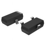 HSMP-4890-TR2G

The activity of extra discounts on wholesale prices is in full swing…
Please fill in your contact information and we will send you the latest wholesale price list.




