 ChipApex | Global Electronic Components Supplier

SEARCH
Search Product
Search Post
— IC芯片 | 连接器 | 传感器 | 被动器件 —
Search productSearch post
— IC芯片 | 连接器 | 传感器 | 被动器件 —
Consult the customer manager about the wholesale price.
consultation hotline:86-132-6715-2157
email:[email protected]
Contact the product manager for consultation. One-stop consultation is available.
Do you want a lower wholesale price? Please send us your inquiry and we will reply immediately.
LMK1C1104DQFT is listed in the Clock Buffers, Drivers range at ChipApex. The manufacturer field lists Texas Instruments. Its product description is IC CLK BUFFER 1:4 250MHZ 8WSON. Review the specifications below when checking this part for your BOM.
The LMK1C1104DQFT is a 1:4 LVCMOS clock buffer from the Texas Instruments LMK1C110x family, housed in an 8-pin WSON (2.00 mm × 2.00 mm) package. It supports supply voltages of 3.3 V, 2.5 V, and 1.8 V, with maximum operating frequencies of 250 MHz at 3.3 V and 200 MHz at lower voltages. Key electrical parameters include a propagation delay of up to 3 ns, output-output skew under 50 ps, and additive jitter ranging from 7.5 fs typical at 3.3 V to 19.2 fs typical at 1.8 V. The device features synchronous output enable control via the 1G pin and includes fail-safe inputs to prevent oscillation without an input signal.
Verify the DQF suffix indicates the 8-pin WSON package configuration. Confirm the T suffix corresponds to the small tape-and-reel carrier containing 250 units per reel. Ensure the orderable part number matches the specific voltage and performance grade required for the target application environment.
Select this component for applications requiring a single-ended LVCMOS input to fan out to four outputs with minimal skew. Compare against LMK1C1102 or LMK1C1103 if fewer outputs are needed, as they share pin compatibility. Consider the LMK1C1104PWR variant if a TSSOP package is preferred over the compact WSON form factor.
This device belongs to the LMK1C110x modular clock buffer family, which also includes 1:2, 1:3, 1:6, and 1:8 variants. The family is designed for backward compatibility with the CDCLVC110x series. The LMK1C1104 specifically provides four buffered outputs, distinguishing it from the two-output LMK1C1102 and three-output LMK1C1103 models within the same footprint.
LMK1C1104DQFR (WSON, 3000-unit reel)
The device incorporates input hysteresis that prevents random oscillation at the outputs in the absence of an input signal. This allows input pins to be left open or driven before VDD is applied without damaging the device.
The maximum input/output frequency is 250 MHz when powered by 3.3 V. For 2.5 V and 1.8 V supply voltages, the maximum frequency is limited to 200 MHz.
Yes, unused LVCMOS outputs can be left floating. This design choice helps reduce overall system component cost and complexity.
Explore related parts through Clock/Timing, Integrated Circuits (ICs), all product categories, ChipApex homepage.
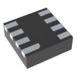 LMK1C1104DQFT

The activity of extra discounts on wholesale prices is in full swing…
Please fill in your contact information and we will send you the latest wholesale price list.





