 ChipApex | Global Electronic Components Supplier
SEARCH
Search Product
Search Post
— IC芯片 | 连接器 | 传感器 | 被动器件 —
Search productSearch post
— IC芯片 | 连接器 | 传感器 | 被动器件 —
Consult the customer manager about the wholesale price.
consultation hotline:86-132-6715-2157
email:[email protected]
Contact the product manager for consultation. One-stop consultation is available.
Do you want a lower wholesale price? Please send us your inquiry and we will reply immediately.
The LTC1068-25CG#TRPBF is a clock-tunable, quad second-order switched-capacitor filter building block in a 28-lead SSOP package. It features four matched sections with a nominal clock-to-center frequency ratio of 25:1. The device operates on supply voltages ranging from 3.14V to ±5.5V, drawing typical power supply currents between 3.5mA and 9.5mA depending on the configuration. Internal op amps provide a gain-bandwidth product of 6MHz and a slew rate of 10V/µs. The center frequency error is typically ±0.3% with a maximum of ±0.8%. Noise performance for Q ≤ 5 is specified at 90µVRMS.
Verify the specific suffix #TRPBF indicates tape and reel packaging when sourcing components. Confirm that the CG designation corresponds to the commercial temperature range of 0°C to 70°C. Ensure the clock source meets the required duty cycle and voltage threshold specifications for the selected supply voltage to maintain filter accuracy.
Select this variant when a 25:1 clock-to-center frequency ratio is required for higher frequency applications compared to other family members. Consider the internal op amp limitations, such as the 6MHz gain-bandwidth product, when designing for high-Q or high-frequency responses. Evaluate the maximum Q versus center frequency graphs to ensure the design stays within operational limits for the chosen supply voltage.
This component belongs to the LTC1068 series of universal switched-capacitor filters. The series includes variants with different nominal ratios, specifically the LTC1068-200, LTC1068, and LTC1068-50. All family members share similar pinouts and architectural features but differ in their default clock-to-center frequency scaling factors.
Direct replacements must match the 28-lead SSOP package and the 25:1 clock ratio. Other members of the LTC1068 family offer different ratios and are not functionally equivalent without circuit redesign. No alternative part numbers are explicitly listed as direct substitutes in the provided documentation.
The maximum clock frequency is 5.6 MHz when the quality factor (Q) is less than or equal to 1.6 and the device is operated in Mode 1 with a ±5V supply.
In single supply operation, the AGND pin is biased internally to 0.5 times the positive supply voltage (V+) and should be bypassed to the analog ground plane with at least a 0.47µF capacitor.
Yes, external resistors can be used to modify the nominal 25:1 ratio, allowing for adjustments above or below the standard value depending on the selected operating mode.
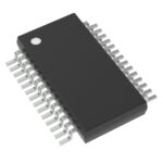 LTC1068-25CG#TRPBF
The activity of extra discounts on wholesale prices is in full swing…
Please fill in your contact information and we will send you the latest wholesale price list.





