 ChipApex | Global Electronic Components Supplier

SEARCH
Search Product
Search Post
— IC芯片 | 连接器 | 传感器 | 被动器件 —
Search productSearch post
— IC芯片 | 连接器 | 传感器 | 被动器件 —
Consult the customer manager about the wholesale price.
consultation hotline:86-132-6715-2157
email:[email protected]
Contact the product manager for consultation. One-stop consultation is available.
Do you want a lower wholesale price? Please send us your inquiry and we will reply immediately.
M-8870-02SMTR is listed in the Telecom range at ChipApex. The manufacturer field lists IXYS Integrated Circuits Division. Its product description is IC TELECOM INTERFACE 18SOIC. Review the specifications below when checking this part for your BOM.
The M-8870-02SMTR is a full DTMF receiver manufactured by IXYS Integrated Circuits Division (Clare) in an 18-pin plastic SOIC tape and reel package. It integrates bandsplit filters and a digital decoder to detect and decode all 16 DTMF tone pairs into a 4-bit code. The device operates on a single 5V supply with typical operating current of 3.0 mA and maximum power consumption of 35 mW. It features adjustable acquisition and release times, dial tone suppression, and a low-cost 3.579545 MHz time base. The -02 variant includes power-down and inhibit modes.
Verify the specific ordering suffix SMTR confirms the 18-pin plastic SOIC package and tape and reel packaging format. Confirm that the -02 designation is present to ensure the inclusion of power-down and inhibit mode functionality on pins 5 and 6. Cross-reference the manufacturer part number against official Clare or IXYS documentation to validate component authenticity.
Select this component when a complete DTMF receiver solution is required with minimal external parts. The -02 version is necessary if system design requires active power-down control or inhibition of the fourth column digits. Ensure the application can accommodate the 3.579545 MHz crystal requirement and the 18-pin SOIC footprint constraints.
The M-8870 series consists of CMOS DTMF receivers designed for telecommunications applications. The M-8870-02SMTR represents the surface-mount variant of the -02 model, which adds control features not found in the standard M-8870-01. This family utilizes switched capacitor technology to replace traditional analog filter components, reducing board space and cost.
Public confirmed substitute part numbers are not available in the provided source material.
Applying a logic high to pin 6 (PD*) places the device into standby mode, dropping power consumption to less than 0.5 mW by stopping the oscillator and filter functions.
Pin 5 (INH*) inhibits the detection of tones representing keys A, B, C, and D (1633 Hz). When held high, the output code remains the same as the previously detected code.
The device requires a 3.579545 MHz color burst crystal connected between pins 7 (OSC1) and 8 (OSC2) to complete the internal oscillator circuit.
Explore related parts through Interface, Integrated Circuits (ICs), all product categories, ChipApex homepage.
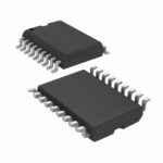 M-8870-02SMTR

The activity of extra discounts on wholesale prices is in full swing…
Please fill in your contact information and we will send you the latest wholesale price list.






