 ChipApex | Global Electronic Components Supplier
SEARCH
Search Product
Search Post
— IC芯片 | 连接器 | 传感器 | 被动器件 —
Search productSearch post
— IC芯片 | 连接器 | 传感器 | 被动器件 —
Consult the customer manager about the wholesale price.
consultation hotline:86-132-6715-2157
email:[email protected]
Contact the product manager for consultation. One-stop consultation is available.
Do you want a lower wholesale price? Please send us your inquiry and we will reply immediately.
The MAX3250EAI+ is a dual-die, ±50V isolated RS-232 transceiver operating on a single 3.0V to 5.5V logic supply. It provides two drivers and two receivers with a guaranteed data rate of 250kbps. Power transfers across the isolation barrier via external ±100V capacitors (C1, C2). The device features an open-drain FAULT output that triggers when the voltage difference between GND and ISOCOM exceeds 55V. It operates within a temperature range of -40°C to +85°C and is housed in a 28-pin SSOP package.
Verify the specific suffix 'EAI+' confirms the extended industrial temperature range (-40°C to +85°C) and lead-free/RoHS compliance. Confirm the package type matches the required 28-pin SSOP footprint. Ensure external capacitor ratings meet the specified minimums for proper isolation performance.
Select this component when high common-mode noise rejection is required without using optocouplers. Verify that the application requires only two drivers and two receivers. Ensure the PCB layout can accommodate the necessary 20mil air gap between logic and isolated sides to maintain the ±50V isolation rating.
This part belongs to the MAX3250 family of isolated RS-232 transceivers. The 'E' suffix denotes the extended temperature range variant, while 'AI' specifies the 28-pin SSOP package. The '+' indicates RoHS-compliant manufacturing. It serves as a direct replacement for traditional opto-isolated interfaces in space-constrained designs.
Direct functional replacements include other Maxim Integrated isolated RS-232 transceivers such as the MAX3251 or MAX3252, which offer similar isolation and interface counts but may differ in pinout or specific electrical characteristics.
Power is transferred from the logic side to the isolated side using external ±100V capacitors (C1 and C2). The device drives AC waveforms into these capacitors, which are rectified on the isolated side to generate the internal ISOVCC supply.
The SHDN (Shutdown) pin controls the low-power mode. Driving it low enters shutdown, reducing supply current to 20µA and placing receiver/transmitter outputs in a high-impedance state. Driving it high enables normal operation.
If the differential voltage exceeds the limit, the FAULT output goes active (low) to signal an overvoltage condition. This allows the processor to monitor the status and prevent potential damage or erroneous operation.
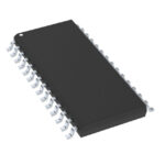 MAX3250EAI+
The activity of extra discounts on wholesale prices is in full swing…
Please fill in your contact information and we will send you the latest wholesale price list.





