 ChipApex | Global Electronic Components Supplier
SEARCH
Search Product
Search Post
— IC芯片 | 连接器 | 传感器 | 被动器件 —
Search productSearch post
— IC芯片 | 连接器 | 传感器 | 被动器件 —
Consult the customer manager about the wholesale price.
consultation hotline:86-132-6715-2157
email:[email protected]
Contact the product manager for consultation. One-stop consultation is available.
Do you want a lower wholesale price? Please send us your inquiry and we will reply immediately.
The MAX3292CSD is a full-duplex RS-485/RS-422 transceiver featuring driver preemphasis circuitry to reduce intersymbol interference. It operates from a single +5V supply and supports data rates up to 10Mbps. The device includes a fail-safe receiver that guarantees a logic-high output when the input is open, and a 1/4-unit-load receiver impedance allows for up to 128 transceivers on the bus. It offers a low-current shutdown mode reducing supply current to 100nA. The component is housed in a 14-pin SO package and functions within an operating temperature range of 0°C to +70°C.
Verify the specific suffix 'CSD' corresponds to the commercial temperature grade (0°C to +70°C) and the 14-pin Small Outline package. Confirm the manufacturer designation as Analog Devices Inc./Maxim Integrated. Ensure the component meets RoHS requirements if applicable to the project specifications before finalizing procurement.
Select the MAX3292CSD over the MAX3291 variant when programmable preemphasis timing is required via an external resistor. This model is suitable for applications needing full-duplex operation at speeds up to 10Mbps with a standard +5V supply. Consider the 1/4-unit-load receiver capability for high-node-count bus configurations.
The MAX3292CSD belongs to the MAX3291/MAX3292 family of high-speed RS-485/RS-422 transceivers. It shares pin compatibility with legacy devices such as the SN75180, MAX489, MAX491, MAX3080, MAX3083, MAX3086, and MAX1482, facilitating direct upgrades in existing designs requiring enhanced transmission performance.
Public confirmed substitutes include MAX3291CSD, MAX3086CSD, and MAX3491CSD-G002. Verify functional equivalence regarding preemphasis capabilities and voltage levels when replacing this component.
The preemphasis interval is set using an external resistor connected between the PSET and VCC pins. A capacitor should also be placed from PSET to VCC for bypassing.
The MAX3292 features a 1/4-unit-load receiver input impedance, allowing up to 128 transceivers to be connected on a single communication line.
Shutdown is initiated by driving the Receiver Enable (RE) pin high and the Driver Enable (DE) pin low simultaneously.
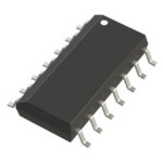 MAX3292CSD
The activity of extra discounts on wholesale prices is in full swing…
Please fill in your contact information and we will send you the latest wholesale price list.





