ChipApex | Global Electronic Components Supplier

SEARCH
Search Product
Search Post
— IC芯片 | 连接器 | 传感器 | 被动器件 —
Search productSearch post
— IC芯片 | 连接器 | 传感器 | 被动器件 —
Consult the customer manager about the wholesale price.
consultation hotline:86-132-6715-2157
email:[email protected]
Contact the product manager for consultation. One-stop consultation is available.
Do you want a lower wholesale price? Please send us your inquiry and we will reply immediately.
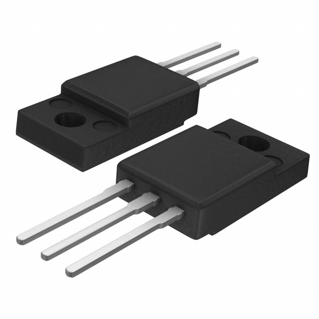
MBRF20H100CTG is listed in the Diode Arrays range at ChipApex. The manufacturer field lists onsemi. Its product description is DIODE ARR SCHOT 100V 10A TO220FP. Review the specifications below when checking this part for your BOM.
The MBRF20H100CTG is a dual common cathode Schottky barrier rectifier manufactured by onsemi. It features a TO-220 Fullpak (TO-220FP) package with an isolated tab for heat dissipation. The device supports a peak repetitive reverse voltage of 100 V and provides a total average rectified forward current of 20 A, distributed as 10 A per diode leg at a case temperature of 162°C. It withstands a nonrepetitive peak surge current of 250 A and operates at junction temperatures up to 175°C. The maximum thermal resistance from junction to case is 2.5°C/W.
Verify the specific package style matches the design requirements, as this part number corresponds to the TO-220 Fullpak variant. Confirm that the application environment stays within the specified thermal limits to maintain reliability. Check for any recent obsolescence notices or alternative recommendations from the manufacturer before finalizing procurement plans.
Select this component when a dual common cathode configuration is required for synchronous rectification or freewheeling applications. Ensure the PCB layout accommodates the TO-220FP footprint and allows adequate airflow or heatsinking to manage the thermal resistance. Validate that the 100 V rating exceeds the circuit's peak reverse voltage under all operating conditions.
This device belongs to the MBR20H100CT family of Switch-mode Power Rectifiers. Other members include the standard TO-220 MBR20H100CTG and the surface-mount D2PAK MBRB20H100CTT4G. The MBRF20H100CTG specifically utilizes the fullpak variant for enhanced mounting stability and thermal performance compared to the standard through-hole version.
Consult the official datasheet for discontinued status updates. Verify pinout compatibility and thermal resistance values when substituting with similar Schottky rectifiers from other manufacturers.
The maximum thermal resistance from junction to case is 2.5°C/W.
Standard versions are not explicitly qualified for automotive use; however, the NRVBB prefix variant is AEC-Q101 qualified and PPAP capable.
The total average rectified forward current is 20 A, which is split between the two diodes, allowing 10 A per leg at a case temperature of 162°C.
Explore related parts through Rectifiers, Diodes, Discrete Semiconductor Products, all product categories.
 MBRF20H100CTG

The activity of extra discounts on wholesale prices is in full swing…
Please fill in your contact information and we will send you the latest wholesale price list.