 ChipApex | Global Electronic Components Supplier

SEARCH
Search Product
Search Post
— IC芯片 | 连接器 | 传感器 | 被动器件 —
Search productSearch post
— IC芯片 | 连接器 | 传感器 | 被动器件 —
Consult the customer manager about the wholesale price.
consultation hotline:86-132-6715-2157
email:[email protected]
Contact the product manager for consultation. One-stop consultation is available.
Do you want a lower wholesale price? Please send us your inquiry and we will reply immediately.
MC100ES6039DW is listed in the Clock Generators, PLLs, Frequency Synthesizers range at ChipApex. The manufacturer field lists NXP USA Inc.. Its product description is IC CLOCK GENERATOR 20SOIC. Review the specifications below when checking this part for your BOM.
The MC100ES6039DW is a low skew clock generation chip from the 100E series, manufactured by Freescale Semiconductor. It provides ÷2/4 and ÷4/6 division ratios with four true differential outputs in a 20-lead SOIC package. The device supports ECL, PECL, HSTL, and LVDS input signals, operating within a frequency range exceeding 1.0 GHz. Key electrical parameters include a maximum output-to-output skew of 50 ps and propagation delays ranging from 500 to 875 ps depending on the signal path. Power supply requirements are VCC = 0 V with VEE = -3.135 V to -3.8 V for ECL mode, or VCC = 3.135 V to 3.8 V with VEE = 0 V for PECL mode.
Verify that the ordering suffix 'DW' corresponds to the 20-lead SOIC package (Case 751D-07). Confirm RoHS compliance status if required, as standard versions may not be lead-free compared to the 'EG' suffix variants. Ensure power supply connections for all VCC and VEE pins are externally connected to guarantee proper operation.
Select this component when sub-nanosecond skew is critical between multiple divided clock outputs. The internal dividers are synchronous, ensuring common output edges are precisely aligned. Consider the ÷2/4 and ÷4/6 configuration options via DIVSELa and DIVSELb inputs. Verify compatibility with the system's input signal type, as the device accepts differential or single-ended ECL, PECL, HSTL, or LVDS signals.
The MC100ES6039 belongs to the 100ES Series, which features temperature compensation. It is designed explicitly for applications demanding low skew clock generation. The device integrates internal pull-up and pull-down resistors (75 kΩ) on input pins to define default states when left open.
Public confirmed substitute part numbers: None identified in verified documentation.
Upon startup, internal flip-flops attain a random state. For systems using multiple ES6039s, the Master Reset (MR) input must be asserted to ensure synchronization. Single-device systems do not require MR exercise due to internal divider design ensuring synchronization between ÷2/4 and ÷4/6 outputs.
The Enable (EN) pin is synchronous, meaning internal dividers are only enabled or disabled when the internal clock is already in the LOW state. This prevents the generation of runt clock pulses during enable/disable transitions.
Yes, the device can be driven by either differential or single-ended ECL, PECL, HSTL, or LVDS input signals. If a single-ended input is used, the VBB output should be connected to the CLK input and bypassed to ground via a 0.01 µF capacitor.
Explore related parts through Clock/Timing, Integrated Circuits (ICs), all product categories, ChipApex homepage.
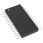 MC100ES6039DW

The activity of extra discounts on wholesale prices is in full swing…
Please fill in your contact information and we will send you the latest wholesale price list.






