 ChipApex | Global Electronic Components Supplier

SEARCH
Search Product
Search Post
— IC芯片 | 连接器 | 传感器 | 被动器件 —
Search productSearch post
— IC芯片 | 连接器 | 传感器 | 被动器件 —
Consult the customer manager about the wholesale price.
consultation hotline:86-132-6715-2157
email:[email protected]
Contact the product manager for consultation. One-stop consultation is available.
Do you want a lower wholesale price? Please send us your inquiry and we will reply immediately.
The MPC9352AC is a 3.3 V or 2.5 V compatible, 1:11 LVCMOS PLL-based clock generator designed for high-performance clock tree applications. It features a fully integrated PLL with output frequencies ranging from 16.67 MHz to 200 MHz and maximum output skew lower than 200 ps. The device supports zero-delay applications by minimizing propagation delay through external feedback configuration. It includes three output banks (A, B, C) with individually configurable frequency dividers via FSEL pins. The component operates within an ambient temperature range of -40°C to +85°C and is housed in a 32-lead LQFP package.
Verify the specific suffix 'AC' against the manufacturer's documentation to confirm lead-free status and RoHS compliance. Confirm availability as this component may be subject to discontinuation notices. Ensure the ordering suffix matches the required environmental rating and packaging type specified in the official datasheet.
Select the MPC9352AC when low output skew (<200 ps) and zero-delay buffering are critical for system timing. Ensure the design accommodates separate power supplies for VCC and VCCA, including the recommended RC filter on the VCCA pin to minimize jitter. Verify that the input reference frequency allows the internal VCO to remain within the 200–400 MHz lock range using the available feedback dividers.
The MPC9352 belongs to the Advanced Clock Drivers family originally developed by Freescale Semiconductor, which was later acquired by NXP USA Inc. The 'AC' suffix typically denotes the Pb-free version of the standard MPC9352 device. This component serves as a fanout buffer and clock multiplier for complex digital systems requiring phase-aligned clock signals.
Public confirmed substitute part numbers are not available in the provided source material.
Zero-delay operation is achieved by connecting one output (e.g., QA0) to the FB_IN pin. The PLL aligns the feedback clock edge with the reference clock input edge, virtually eliminating insertion delay.
An RC filter is recommended on the VCCA pin. For VCC=3.3V, use RF=5–15Ω; for VCC=2.5V, use RF=9–10Ω. A capacitor CF should provide attenuation >40 dB above 100 kHz.
Yes. Each output can drive one parallel terminated 50Ω line or up to two series terminated 50Ω lines, effectively doubling the fanout capability compared to parallel termination alone.
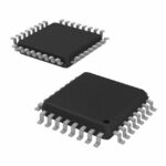 MPC9352AC

The activity of extra discounts on wholesale prices is in full swing…
Please fill in your contact information and we will send you the latest wholesale price list.





