 ChipApex | Global Electronic Components Supplier
SEARCH
Search Product
Search Post
— IC芯片 | 连接器 | 传感器 | 被动器件 —
Search productSearch post
— IC芯片 | 连接器 | 传感器 | 被动器件 —
Consult the customer manager about the wholesale price.
consultation hotline:86-132-6715-2157
email:[email protected]
Contact the product manager for consultation. One-stop consultation is available.
Do you want a lower wholesale price? Please send us your inquiry and we will reply immediately.
The PDTA124XQC-QZ is a PNP Resistor-Equipped Transistor (RET) from the Nexperia PDTA143X/123J/143Z/114Y/124XQC-Q series. It integrates bias resistors into an ultra-small DFN1412D-3 (SOT8009) leadless SMD package with side-wettable flanks. Key electrical parameters include a collector-emitter voltage of -50 V, output current of -100 mA, and total power dissipation up to 360 mW on a 35 µm copper PCB. The built-in resistors are R1 = 22 kΩ and R2 = 47 kΩ, yielding a ratio of approximately 2.13. The device features a minimum DC current gain (hFE) of 80 at IC = -5 mA and VCE = -5 V, with a typical transition frequency of 180 MHz.
Verify the specific ordering suffix against the manufacturer's latest documentation to confirm packaging details such as reel or cut tape configuration. Ensure the procurement channel provides valid traceability records consistent with Nexperia's quality standards. Cross-reference the marking code '6F' on the physical component to validate authenticity before integration into production lines.
Select this component when space constraints require a compact footprint alongside integrated biasing functionality. The 22 kΩ input resistor value suits applications requiring specific base drive characteristics compared to other variants in the series. Verify that the -50 V rating aligns with the system's maximum operating voltages and that the thermal resistance values meet the application's heat dissipation requirements.
This part belongs to the PDTA143X/123J/143Z/114Y/124XQC-Q series of PNP resistor-equipped transistors. It serves as the NPN complement counterpart to the PDTC124XQC-Q within the same family. The series offers various resistor combinations tailored for different digital switching needs while maintaining a standardized ultra-small package form factor.
Direct substitutes within the same series include PDTA143XQC-Q, PDTA123JQC-Q, PDTA143ZQC-Q, and PDTA114YQC-Q. These alternatives share identical package dimensions and pinout configurations but differ in internal resistor values. Verify that the alternative resistor ratios meet the specific circuit design requirements before substitution.
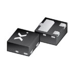 PDTA124XQC-QZ
The activity of extra discounts on wholesale prices is in full swing…
Please fill in your contact information and we will send you the latest wholesale price list.





