 ChipApex | Global Electronic Components Supplier
SEARCH
Search Product
Search Post
— IC芯片 | 连接器 | 传感器 | 被动器件 —
Search productSearch post
— IC芯片 | 连接器 | 传感器 | 被动器件 —
Consult the customer manager about the wholesale price.
consultation hotline:86-132-6715-2157
email:[email protected]
Contact the product manager for consultation. One-stop consultation is available.
Do you want a lower wholesale price? Please send us your inquiry and we will reply immediately.
The PDTC114YQBZ is an NPN resistor-equipped transistor (RET) from the Nexperia PDTC143X/123J/143Z/114Y/124XQB series. It features a built-in bias resistor R1 of 10 kΩ and a bias resistor ratio (R2/R1) of 4.7, with R2 nominally at 47 kΩ. The device supports a collector-emitter voltage (VCEO) of 50 V and a continuous output current (IO) of 100 mA. It is housed in a DFN1110D-3 (SOT8015) leadless surface-mount package measuring 1.1 x 1.0 x 0.48 mm. Key electrical characteristics include a DC current gain (hFE) minimum of 100 at IC = 5 mA and VCE = 5 V, and a transition frequency (fT) typical value of 230 MHz.
Verify the specific ordering suffix against the manufacturer's latest documentation to ensure correct packaging and tape-and-reel specifications. Confirm that the DFN1110D-3 footprint matches the target PCB layout requirements. Check for any recent product change notifications regarding marking codes or thermal characteristics before finalizing procurement.
Select this component when a compact NPN switch with integrated base biasing is required. The 10 kΩ input resistor provides a specific drive current characteristic distinct from other variants in the series. Ensure the application voltage does not exceed the 50 V collector-emitter rating and that the thermal resistance values align with the expected power dissipation in free air or on the PCB.
This part belongs to the Nexperia PDTC143X/123J/143Z/114Y/124XQB family of 50 V, 100 mA NPN resistor-equipped transistors. The 'Y' designation specifically indicates the 10 kΩ / 47 kΩ resistor configuration within this series. The 'QB' suffix denotes the DFN1110D-3 (SOT8015) package variant with side-wettable flanks, distinguishing it from older SOT packages.
PDTC114YT-QR offers similar electrical performance but utilizes a SOT-23 package instead of the DFN1110D-3 form factor. Designers must account for the physical footprint differences and potential changes in thermal resistance when substituting between these package types.
For the PDTC114YQBZ, the internal bias resistor R2 has a nominal value of 47 kΩ, resulting in a bias resistor ratio (R2/R1) of 4.7 given the 10 kΩ R1.
No. Unless explicitly stated otherwise in the data sheet, this product is not suitable for automotive use and is not qualified according to automotive testing or application requirements.
The maximum junction temperature (Tj) for the PDTC114YQBZ is 150 °C.
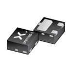 PDTC114YQBZ
The activity of extra discounts on wholesale prices is in full swing…
Please fill in your contact information and we will send you the latest wholesale price list.





