 ChipApex | Global Electronic Components Supplier
SEARCH
Search Product
Search Post
— IC芯片 | 连接器 | 传感器 | 被动器件 —
Search productSearch post
— IC芯片 | 连接器 | 传感器 | 被动器件 —
Consult the customer manager about the wholesale price.
consultation hotline:86-132-6715-2157
email:[email protected]
Contact the product manager for consultation. One-stop consultation is available.
Do you want a lower wholesale price? Please send us your inquiry and we will reply immediately.
The Microchip Technology QT60240-ATG is a digital burst mode charge-transfer touch sensor IC designed for matrix layout controls. It supports up to 24 keys within an 8x3 grid and utilizes patented spread-spectrum transverse sensing technology. The device operates on a supply voltage of 1.8V to 5.5V, with power consumption as low as 40µA in low-power mode. It features an I2C slave interface operating at 100kHz for data extraction and configuration. The component is housed in a 32-pin 5mm x 5mm MLF package and functions reliably across a temperature range of -40°C to +85°C.
Verify the specific ATG suffix against official documentation to confirm exact manufacturing lot or regional compliance details. Ensure compatibility with the 32-pin MLF footprint during procurement planning. Confirm availability status with authorized distributors as lead times may vary based on production cycles.
Select this model when a maximum of 24 independent touch inputs are required within a compact form factor. It is suitable for applications needing high moisture tolerance and adjacent metal compatibility. Consider the I2C interface requirements and verify that the host system can support the necessary pull-up resistors and address configurations.
The QT60240 belongs to the QMatrix family of touch sensor controllers from Microchip Technology. It shares architectural similarities with the QT60160 but offers double the key capacity. This series is engineered for low-cost mobile and consumer electronics, providing a complete signal processing solution without external amplifiers.
The QT60160 serves as a functional substitute if fewer than 16 keys are required, sharing identical pinouts and software compatibility. Verify that the replacement part number matches the specific thermal and electrical specifications needed for the target application environment.
Signal saturation occurs if the Cs capacitor voltage drops below -0.25V. This can be mitigated by reducing the burst length, increasing the Cs value, or adjusting the PCB layout to reduce stray capacitance.
This hard-wired feature uses frequency chirping to drastically reduce EMI effects on sensor keys while simultaneously spreading RF emissions, ensuring robust operation in noisy environments.
Yes, unused Y lines should be left open, and their corresponding Cs capacitors may be omitted. However, all active signal-related discrete parts must be placed very close to the chip body.
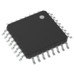 QT60240-ATG
The activity of extra discounts on wholesale prices is in full swing…
Please fill in your contact information and we will send you the latest wholesale price list.





