ChipApex | Global Electronic Components Supplier
SEARCH
Search Product
Search Post
— IC芯片 | 连接器 | 传感器 | 被动器件 —
Search productSearch post
— IC芯片 | 连接器 | 传感器 | 被动器件 —
Consult the customer manager about the wholesale price.
consultation hotline:86-132-6715-2157
email:[email protected]
Contact the product manager for consultation. One-stop consultation is available.
Do you want a lower wholesale price? Please send us your inquiry and we will reply immediately.
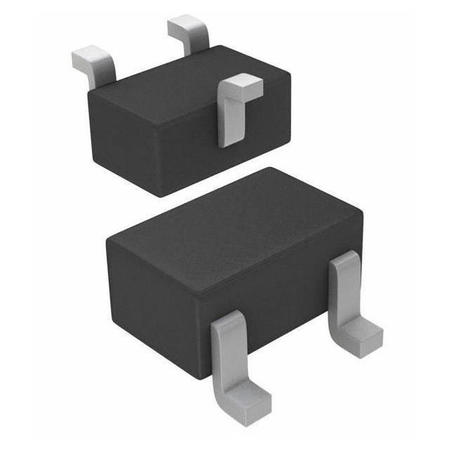
The RN1311,LXHF is a single NPN epitaxial planar silicon bias resistor built-in transistor (BRT) manufactured by Toshiba Semiconductor and Storage. Designed for switching, inverter, interfacing, and driver circuits, it integrates an internal bias network to simplify design. The device features a collector-emitter voltage of 50 V, a continuous collector current of 100 mA, and a power dissipation of 100 mW. It utilizes the USM surface-mount package with a typical input resistance of 10 kΩ. The component is qualified under AEC-Q101 standards for automotive applications.
Verify the specific ordering suffix against the manufacturer's official orderable part number list to confirm AEC-Q101 automotive qualification status. Ensure the selected variant matches the required application category, as general-use and automotive versions share similar electrical characteristics but differ in reliability standards. Confirm RoHS compliance requirements prior to procurement.
Select this component when a compact NPN solution with integrated base biasing is required for low-power switching or logic interfacing. The 10 kΩ input resistance suits standard logic levels. Consider the USM package dimensions for PCB layout constraints. Verify that the 100 mA collector current and 100 mW power dissipation ratings exceed the maximum expected load conditions in the target circuit design.
This device belongs to the RN13xx series of bias resistor built-in transistors from Toshiba. It serves as the NPN equivalent to the RN23xx series. The LXHF suffix indicates a specific packaging and handling format within the broader RN1311 product family, which includes variants like LF and LXGF.
Direct replacements include other single NPN BRTs with 50V VCEO, 100mA IC, and ~10kΩ R1. Verify pinout compatibility (Base-Emitter-Collector) and package footprint (USM/SOT-323). Check if the substitute meets AEC-Q101 requirements if automotive qualification is mandatory.
The typical input resistance (R1) for the RN1311 is 10 kΩ.
Yes, the RN1311,LXHF is listed as AEC-Q101 qualified for automotive use in the official datasheet.
The maximum collector-emitter saturation voltage (VCE(sat)) is 0.3 V at IC = 5 mA and IB = 0.25 mA.
 RN1311,LXHF
The activity of extra discounts on wholesale prices is in full swing…
Please fill in your contact information and we will send you the latest wholesale price list.