ChipApex | Global Electronic Components Supplier
SEARCH
Search Product
Search Post
— IC芯片 | 连接器 | 传感器 | 被动器件 —
Search productSearch post
— IC芯片 | 连接器 | 传感器 | 被动器件 —
Consult the customer manager about the wholesale price.
consultation hotline:86-132-6715-2157
email:[email protected]
Contact the product manager for consultation. One-stop consultation is available.
Do you want a lower wholesale price? Please send us your inquiry and we will reply immediately.
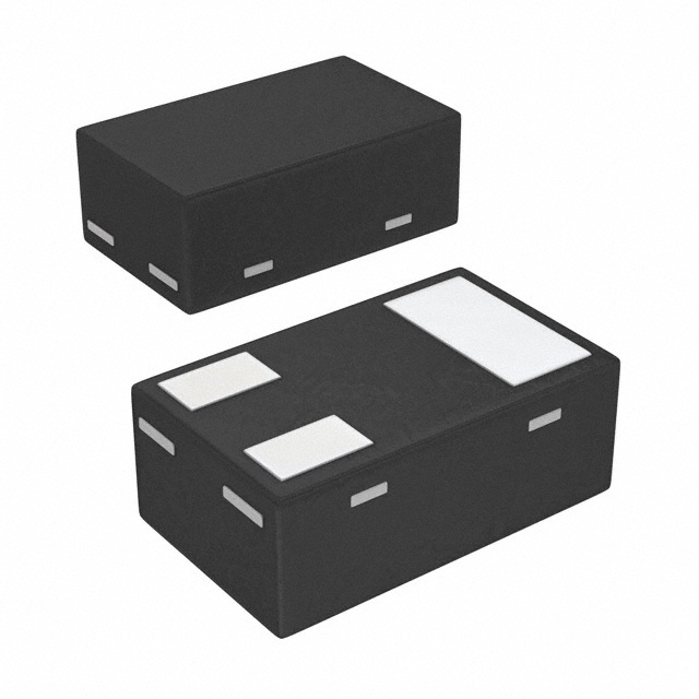
The RN2101ACT(TPL3) is a PNP digital transistor manufactured by Toshiba Semiconductor and Storage, featuring built-in bias resistors to simplify circuit design. It operates with a maximum collector-emitter voltage of 50 V and a continuous collector current of 100 mA. The device utilizes an SC-70 (SOT-323) surface-mount package, ensuring compact integration in space-constrained applications. Key electrical characteristics include a minimum DC current gain (hFE) of 70 at specified test conditions and a transition frequency of 200 MHz. The internal resistor network typically consists of two 10 kΩ resistors, providing a fixed bias ratio for consistent switching performance.
Verify the specific ordering suffix TPL3 against the manufacturer's latest datasheet to confirm tape-and-reel packaging specifications. Ensure compatibility with RoHS directives and check for any recent lifecycle status changes, such as obsolescence or recommended alternatives, before finalizing procurement plans.
Select this component when a PNP configuration with integrated biasing is required for compact designs. Compare the 100 mA current rating and 50 V breakdown voltage against load requirements. Consider the SC-70 footprint constraints and verify that the 200 MHz frequency response meets the signal speed demands of the target application.
This part belongs to Toshiba's RN series of digital transistors, which are designed to replace discrete resistor-transistor combinations. The RN2101ACT variant specifically denotes a PNP type with a standard 1:1 resistor ratio. These components are widely used in industrial and consumer markets where space efficiency and simplified schematic design are critical priorities.
Direct substitutes may include other PNP digital transistors with similar 50V/100mA ratings and SC-70 packages, such as those from ON Semiconductor or Rohm. Verify pinout compatibility and resistor values before substitution to ensure circuit functionality remains unchanged.
The RN2101ACT typically features a built-in bias resistor ratio of 1:1, consisting of two 10 kΩ resistors.
Yes, it has a transition frequency (fT) of 200 MHz, making it suitable for moderate to high-speed switching applications.
The maximum power dissipation is typically rated at 150 mW, depending on the ambient temperature and thermal resistance of the PCB layout.
 RN2101ACT(TPL3)
The activity of extra discounts on wholesale prices is in full swing…
Please fill in your contact information and we will send you the latest wholesale price list.