ChipApex | Global Electronic Components Supplier
SEARCH
Search Product
Search Post
— IC芯片 | 连接器 | 传感器 | 被动器件 —
Search productSearch post
— IC芯片 | 连接器 | 传感器 | 被动器件 —
Consult the customer manager about the wholesale price.
consultation hotline:86-132-6715-2157
email:[email protected]
Contact the product manager for consultation. One-stop consultation is available.
Do you want a lower wholesale price? Please send us your inquiry and we will reply immediately.
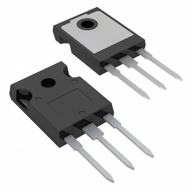
The SB4045PT_T0_00001 is a Schottky barrier rectifier from the SB4020PT series manufactured by Panjit International Inc. It features a TO-247AD/TO-3P molded plastic case with solder-plated terminals. The device provides a maximum average forward current of 40 A at a case temperature of 90°C and supports a maximum repetitive peak reverse voltage of 45 V. Electrical characteristics include a maximum forward voltage of 0.60 V at 20 A per leg, a typical thermal resistance of 1.5 °C/W, and a peak forward surge current capability of 350 A for an 8.3 ms half-sine wave.
Verify the specific part number suffix against official documentation to confirm packaging configuration. The T0 designation indicates Tape and Reel packing on a 13-inch reel compliant with RoHS directives. Confirm that the component meets the required environmental standards for the intended deployment environment before finalizing procurement orders.
Select this component when a 45 V blocking voltage and 40 A continuous current rating are required in a TO-247 package. Ensure the application operates within the specified junction temperature range of -55°C to +150°C. Derate the forward current by 20% if the load is capacitive to maintain safe operating conditions.
This component belongs to the SB4020PT series, which encompasses devices ranging from 20 V to 60 V reverse voltage ratings. All members of this series share identical physical dimensions and thermal characteristics while varying in their voltage blocking capabilities. The series is designed for surface mount or panel mount integration using standard mounting hardware compatible with the TO-247 footprint.
Cross-reference other SB4020PT series variants such as SB4040PT or SB4050PT if voltage requirements differ. Verify that any substitute maintains the same TO-247AD mechanical outline and thermal resistance specifications to ensure compatibility with existing heatsinking solutions.
The maximum DC blocking voltage is 40 V, while the maximum repetitive peak reverse voltage is rated at 45 V.
The device uses a flame retardant epoxy molding compound with a UL 94V-O flammability classification to enhance safety and durability.
When used with a capacitive load, the forward current must be derated by 20% to ensure reliable operation.
 SB4045PT_T0_00001
The activity of extra discounts on wholesale prices is in full swing…
Please fill in your contact information and we will send you the latest wholesale price list.