 ChipApex | Global Electronic Components Supplier

SEARCH
Search Product
Search Post
— IC芯片 | 连接器 | 传感器 | 被动器件 —
Search productSearch post
— IC芯片 | 连接器 | 传感器 | 被动器件 —
Consult the customer manager about the wholesale price.
consultation hotline:86-132-6715-2157
email:[email protected]
Contact the product manager for consultation. One-stop consultation is available.
Do you want a lower wholesale price? Please send us your inquiry and we will reply immediately.
SBR4045CT is listed in the Diode Arrays range at ChipApex. The manufacturer field lists Diodes Incorporated. Its product description is DIODE ARRAY SBR 45V 20A TO-220-3. Review the specifications below when checking this part for your BOM.
The SBR4045CT is a dual common cathode Super Barrier Rectifier manufactured by Diodes Incorporated. It features a 45 V peak repetitive reverse voltage rating and an average rectified output current of 20 A per leg, totaling 40 A for the device. The component utilizes patented Super Barrier technology to achieve a low forward voltage drop of 0.47 V at 20 A and 25°C. It operates within a temperature range of -65°C to +150°C and is housed in a TO-220AB through-hole package.
Verify the specific ordering suffix against the manufacturer's documentation to confirm the exact case style and packaging configuration. Confirm RoHS compliance status and environmental declarations such as halogen-free requirements prior to procurement. Ensure thermal management solutions align with the specified junction-to-case thermal resistance values for the intended application environment.
Select this component when low conduction losses and high efficiency are required in low-voltage, high-frequency environments. The dual common cathode configuration supports center-tapped transformer topologies. Evaluate the thermal resistance characteristics relative to the expected ambient temperatures and derating curves to ensure reliable operation under continuous load conditions.
This part belongs to the SBR40 series of Super Barrier Rectifiers from Diodes Incorporated. It represents a specialized class of silicon rectifiers designed to outperform standard Schottky diodes in terms of leakage current stability at elevated temperatures while maintaining low forward voltage characteristics suitable for modern power conversion systems.
SBR4045CTFP (ITO-220AB package variant)
The maximum non-repetitive peak forward surge current is 280 A for an 8.3 ms single half sine-wave superimposed on rated load.
The typical forward voltage drop increases from 0.47 V at 25°C to 0.50 V at 125°C when tested at a forward current of 20 A.
No isolation voltage is specified for the TO-220AB package; however, the ITO-220AB variant specifies an isolation voltage of 2000 VAC from terminal to heatsink.
Explore related parts through Rectifiers, Diodes, Discrete Semiconductor Products, all product categories.
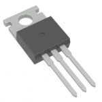 SBR4045CT

The activity of extra discounts on wholesale prices is in full swing…
Please fill in your contact information and we will send you the latest wholesale price list.





