 ChipApex | Global Electronic Components Supplier
SEARCH
Search Product
Search Post
— IC芯片 | 连接器 | 传感器 | 被动器件 —
Search productSearch post
— IC芯片 | 连接器 | 传感器 | 被动器件 —
Consult the customer manager about the wholesale price.
consultation hotline:86-132-6715-2157
email:[email protected]
Contact the product manager for consultation. One-stop consultation is available.
Do you want a lower wholesale price? Please send us your inquiry and we will reply immediately.
The Si5020-B-GM is a fully integrated, low-power Clock and Data Recovery (CDR) IC designed for high-speed serial communication systems. It extracts timing information from OC-48/12/3, STM-16/4/1, Gigabit Ethernet, or 2.7 Gbps FEC data streams. Operating on a single 2.5 V supply across the industrial temperature range (-40 to 85 °C), it utilizes DSPLL technology to eliminate external loop filter components, ensuring optimal jitter performance. The device features differential CML inputs and outputs, loss-of-lock indication, and powerdown control within a compact 4 mm x 4 mm 20-pin MLP package.
Verify that the ordering suffix matches the required package and temperature grade. The datasheet specifies the 'BM' suffix for the 20-pin MLP package with an operating range of -40 to 85 °C. Confirm that the specific variant ordered corresponds to the intended application requirements regarding voltage levels and interface compatibility.
Select this component for applications requiring a complete CDR solution without external passive loop filter components. Ensure the system provides a stable 2.5 V supply and supports the necessary reference clock frequencies (e.g., 19.44 MHz, 77.76 MHz, or 155.52 MHz). Verify that the input data rate aligns with the configured RATESEL settings for the desired SONET/SDH or Ethernet standard.
The Si5020 belongs to the SiPHY multi-rate CDR family from Silicon Laboratories. It is engineered to replace traditional analog PLL designs by integrating the loop filter digitally. This integration allows for smaller board footprints and improved immunity to board-level noise, making it suitable for dense telecommunications and networking hardware where space and signal integrity are critical constraints.
Publicly confirmed substitute part numbers are not available in the provided documentation. Designers should consult manufacturer resources for cross-reference information or evaluate other devices within the Si5018/Si5010 families if pin-out or feature compatibility is required.
Self-calibration is initiated by forcing a high-to-low transition on the PWRDN/CAL pin while a valid reference clock is supplied. The pin must be held high for at least 1 µs before transitioning low to guarantee calibration.
The REXT pin connects to an external 10 kΩ (1%) resistor tied to ground. This resistor sets the internal bias currents for the device, which helps reduce power consumption compared to implementations using internal resistors.
The LOL output is driven high when the recovered clock frequency deviates from the reference clock by more than the specified threshold (typically 450–750 ppm). It indicates that the PLL has lost frequency lock with the incoming data stream.
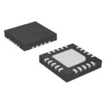 SI5020-B-GM
The activity of extra discounts on wholesale prices is in full swing…
Please fill in your contact information and we will send you the latest wholesale price list.






