 ChipApex | Global Electronic Components Supplier
SEARCH
Search Product
Search Post
— IC芯片 | 连接器 | 传感器 | 被动器件 —
Search productSearch post
— IC芯片 | 连接器 | 传感器 | 被动器件 —
Consult the customer manager about the wholesale price.
consultation hotline:86-132-6715-2157
email:[email protected]
Contact the product manager for consultation. One-stop consultation is available.
Do you want a lower wholesale price? Please send us your inquiry and we will reply immediately.
The SMMUN2134LT1G is a single PNP Bipolar Digital Transistor (BRT) manufactured by onsemi. It integrates a transistor with an internal bias resistor network to simplify circuit design. Key electrical parameters include a maximum collector-emitter voltage (VCEO) of 50 V and a continuous collector current of 100 mA. The device features a typical input resistance of 22 kOhms and a typical resistor ratio of 0.47. Power dissipation is rated at 246 mW, with a minimum DC collector/base gain (hfe) of 80. It operates within a temperature range of -55 C to +150 C and is housed in a surface-mount SOT-23-3 package.
Verify the specific ordering suffix 'T1G' to ensure compliance with tape-and-reel packaging specifications and RoHS directives. Confirm that the SOT-23-3 footprint matches the target PCB layout requirements. Cross-reference the manufacturer datasheet for thermal derating curves relevant to the intended power dissipation limits. Ensure supply chain sources provide original manufacturer documentation to validate authenticity and traceability.
Select this component when a compact PNP digital transistor solution is required for low-power switching tasks. The 50 V rating and 100 mA current capacity suit standard logic-level applications. Consider the 22 kOhm input resistance for compatibility with common microcontroller output drivers. Evaluate the SOT-23-3 package size against available board real estate constraints compared to larger through-hole alternatives.
This part belongs to the MMUN2134L series of Bias Resistor Transistors from onsemi. These devices are engineered to replace individual transistors and external biasing resistors, thereby minimizing assembly steps and reducing overall system cost. The series offers various resistor configurations to accommodate different drive requirements while maintaining a standardized form factor for easy integration into existing designs.
Direct substitutes include other PNP BRTs with similar VCEO and Ic ratings, such as the MMUN2134LT1G. Verify pinout compatibility and internal resistor values before substitution. Alternative packages may require schematic adjustments. Consult manufacturer cross-reference tools for validated equivalent parts meeting identical electrical specifications.
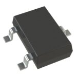 SMMUN2134LT1G
The activity of extra discounts on wholesale prices is in full swing…
Please fill in your contact information and we will send you the latest wholesale price list.






