 ChipApex | Global Electronic Components Supplier
SEARCH
Search Product
Search Post
— IC芯片 | 连接器 | 传感器 | 被动器件 —
Search productSearch post
— IC芯片 | 连接器 | 传感器 | 被动器件 —
Consult the customer manager about the wholesale price.
consultation hotline:86-132-6715-2157
email:[email protected]
Contact the product manager for consultation. One-stop consultation is available.
Do you want a lower wholesale price? Please send us your inquiry and we will reply immediately.
The SN74ALS563BNS is an octal D-type transparent latch with 3-state outputs manufactured by Texas Instruments. It operates within a supply voltage range of 4.5 V to 5.5 V and supports a commercial temperature range of 0°C to 70°C. The device features inverted outputs that follow the complements of data inputs when the latch-enable signal is high, latching at the inverse level when the signal goes low. It utilizes a SOP-20 package for surface-mount applications.
Verify the specific ordering suffix 'N' corresponds to the PDIP package rather than the requested 'SN' designation which implies SOP. Confirm RoHS compliance status and lead finish details via the official TI Package Option Addendum. Ensure the selected variant matches the required operating temperature range and package dimensions for the target PCB layout.
Select this component for designs requiring octal data storage with direct bus driving capabilities. The ALS series offers faster switching speeds compared to standard LS logic while maintaining compatible power consumption levels. Verify that the application requires inverted outputs (Q follows complement of D) as the device does not provide non-inverted outputs.
This part belongs to the Texas Instruments SN54/74ALS563B family of octal D-type transparent latches. The family includes military-grade variants like the SNJ54ALS563B and various packaging options such as CDIP, SOIC, and SOP. The device is part of the broader 54ALS/74ALS logic series known for high-speed performance in bipolar technology.
Direct functional equivalents include the SN74ALS563BDW (SOIC package) and SN74ALS563BN (PDIP package). Cross-family replacements from other manufacturers may require verification of pin compatibility and electrical characteristics against the original datasheet specifications.
The buffered output-enable input places the eight outputs in either a normal logic state or a high-impedance state but does not affect the internal operations of the latches. Data can be retained or entered while outputs are disabled.
While the latch-enable input is high, the Q outputs follow the complements of the data inputs. When the latch-enable is taken low, the outputs are latched at the inverse of the levels set up at the D inputs.
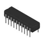 SN74ALS563BNS
The activity of extra discounts on wholesale prices is in full swing…
Please fill in your contact information and we will send you the latest wholesale price list.





