 ChipApex | Global Electronic Components Supplier

SEARCH
Search Product
Search Post
— IC芯片 | 连接器 | 传感器 | 被动器件 —
Search productSearch post
— IC芯片 | 连接器 | 传感器 | 被动器件 —
Consult the customer manager about the wholesale price.
consultation hotline:86-132-6715-2157
email:[email protected]
Contact the product manager for consultation. One-stop consultation is available.
Do you want a lower wholesale price? Please send us your inquiry and we will reply immediately.
SN74HC11DRG4 is listed in the Inverter Gates range at ChipApex. The manufacturer field lists Texas Instruments. Its product description is IC GATE AND 3CH 3-INP 14SOIC. Review the specifications below when checking this part for your BOM.
The SN74HC11DRG4 is a Texas Instruments logic gate containing three independent 3-input AND gates. It operates within a supply voltage range of 2 V to 6 V and supports an operating temperature range from -40°C to +85°C. The device features buffered inputs, balanced CMOS push-pull outputs, and standard CMOS input characteristics. It provides significant power reduction compared to LSTTL logic ICs and supports fanout up to 10 LSTTL loads.
Verify the specific ordering suffix 'G4' against the manufacturer's current documentation to confirm compliance details and material specifications. Ensure the selected package variant matches the required thermal and mechanical constraints for the target application environment.
Select this component when a triple 3-input AND function is required in a compact SOIC-14 package. Consider its wide voltage range and low power consumption as advantages over legacy LSTTL alternatives. Verify that input transition rates meet recommended conditions to prevent excessive current consumption.
This part belongs to the SNx4HC11 family of Triple 3-Input AND Gates manufactured by Texas Instruments. The HC series utilizes high-speed CMOS technology, offering performance comparable to older logic families while significantly reducing power dissipation. The device is designed for general-purpose digital logic applications requiring reliable AND operations.
SN74HC11DR
Unused inputs must not be left floating. They should be terminated to either VCC or ground using pull-up or pull-down resistors to prevent undefined operational states.
Input signals must have fast edge rates as defined in the Recommended Operating Conditions. Slow edge rates can cause oscillations and damaging shoot-through current due to the standard CMOS input structure.
Explore related parts through Logic, Integrated Circuits (ICs), all product categories, ChipApex homepage.
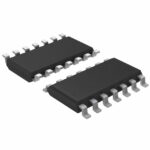 SN74HC11DRG4

The activity of extra discounts on wholesale prices is in full swing…
Please fill in your contact information and we will send you the latest wholesale price list.





