 ChipApex | Global Electronic Components Supplier
SEARCH
Search Product
Search Post
— IC芯片 | 连接器 | 传感器 | 被动器件 —
Search productSearch post
— IC芯片 | 连接器 | 传感器 | 被动器件 —
Consult the customer manager about the wholesale price.
consultation hotline:86-132-6715-2157
email:[email protected]
Contact the product manager for consultation. One-stop consultation is available.
Do you want a lower wholesale price? Please send us your inquiry and we will reply immediately.
The TAS5101IDAP is a true digital stereo audio amplifier featuring an integrated PWM stereo power output stage. It accepts direct digital audio inputs and converts them to high-current analog signals for driving speakers. The device supports various digital audio formats including I2S, left-justified, and right-justified configurations via configurable resistor jumpers. It operates with a PVDD supply range of 12 V to 27 V and a 3.3 V digital logic supply. The amplifier is designed to drive 4-ohm loads with high efficiency and low distortion.
Verify the specific package type and tape/reel specifications against the official datasheet before ordering. Confirm that the component matches the required voltage ratings and pinout configuration for your design. Ensure compatibility with the intended digital audio interface standards. Check for any recent product lifecycle notices or obsolescence warnings from the manufacturer.
Select this component for applications requiring direct digital-to-speaker amplification without external modulators. Consider the 12 V to 27 V supply requirement and the need for low-noise DVDD and PVDD rails. Evaluate the thermal management needs given the power dissipation characteristics. Ensure the system controller can handle the SHUTDOWN and RESET_5K control signals for proper operation.
The TAS5101 is part of Texas Instruments' true digital audio amplifier family. It works in conjunction with digital audio processors and modulators like the TAS5010. The device is often used in evaluation modules such as the TAS5101SE EVM for testing and development purposes. It represents a solution for high-fidelity audio reproduction with simplified system architecture.
Consult the official datasheet for pin-compatible alternatives within the same product family. Verify electrical parameters and package dimensions before substituting. No specific substitute part numbers are confirmed in the provided documentation.
A logic low on the SHUTDOWN pin indicates that the TAS5101 has been shut down due to an error condition such as a short circuit, overtemperature, or low-voltage condition.
The input format is configured using resistor jumpers on the bottom of the PCB, allowing selection between I2S, left-justified, and right-justified modes with varying bit depths.
The device requires a PVDD supply of 12 V to 27 V for the output stage and a 3.3 V DVDD supply for the digital logic.
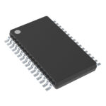 TAS5101IDAP
The activity of extra discounts on wholesale prices is in full swing…
Please fill in your contact information and we will send you the latest wholesale price list.







