 ChipApex | Global Electronic Components Supplier
SEARCH
Search Product
Search Post
— IC芯片 | 连接器 | 传感器 | 被动器件 —
Search productSearch post
— IC芯片 | 连接器 | 传感器 | 被动器件 —
Consult the customer manager about the wholesale price.
consultation hotline:86-132-6715-2157
email:[email protected]
Contact the product manager for consultation. One-stop consultation is available.
Do you want a lower wholesale price? Please send us your inquiry and we will reply immediately.
The TDA8942P is a dual-channel stereo Bridge Tied Load (BTL) audio power amplifier featuring an all-NPN output stage. It delivers 2 × 1.5 W into a 16 Ω load and 2 × 3 W music power into an 8 Ω load at a 9 V supply. The device operates with a supply voltage range of 6 V to 18 V, maintains a fixed voltage gain of 32 dB, and includes standby/mute logic. Key electrical parameters include a quiescent current of 2 mA, standby current under 10 μA, and short-circuit protection for ground, supply, and load conditions.
Verify the component marking against the Philips Semiconductors datasheet revision history to confirm authenticity. Ensure the DIP16 package matches SOT38-1 specifications. Check for physical damage to leads before soldering. Confirm that the source document aligns with the official product data sheet number 9397 750 11707 for accurate pinout and electrical limits.
Select this amplifier when a compact stereo solution with minimal external components is required. The fixed 32 dB gain simplifies circuit design by removing external feedback resistors. Consider the thermal resistance of 57 K/W for heat dissipation planning. The DIP16 package facilitates through-hole mounting on printed-circuit boards compatible with the broader TDA894x family.
Manufactured originally by Philips Semiconductors, now part of NXP USA Inc., the TDA8942P belongs to the TDA894x family of audio amplifiers. It shares PCB compatibility with other variants in the series, allowing a single footprint to accommodate both mono and stereo products. The device represents a cost-effective solution for low-power audio amplification in consumer electronics.
The datasheet notes PCB compatibility within the TDA894x family but does not list specific substitute part numbers. Verify pinout and electrical characteristics against any alternative BTL stereo amplifiers before substitution.
Mute mode is activated by applying a DC voltage to the MODE pin between 3 V and (VCC - 1.5 V). In this state, the amplifier is DC-biased but non-operational, preventing pop-noise during startup.
The internal thermal shutdown protection circuit detects the high temperature and switches the power stage to standby mode (high impedance) to protect the device from damage.
Yes, the inputs can be driven asymmetrical. One input pin must be connected via a capacitor to signal ground, which should be located close to the SVR capacitor ground to minimize switch-on delay.
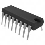 TDA8942P/N1,112
The activity of extra discounts on wholesale prices is in full swing…
Please fill in your contact information and we will send you the latest wholesale price list.





