 ChipApex | Global Electronic Components Supplier
SEARCH
Search Product
Search Post
— IC芯片 | 连接器 | 传感器 | 被动器件 —
Search productSearch post
— IC芯片 | 连接器 | 传感器 | 被动器件 —
Consult the customer manager about the wholesale price.
consultation hotline:86-132-6715-2157
email:[email protected]
Contact the product manager for consultation. One-stop consultation is available.
Do you want a lower wholesale price? Please send us your inquiry and we will reply immediately.
The TS5USBC400YFPR is a dual 2:1 USB 2.0 multiplexer/demultiplexer switch manufactured by Texas Instruments, designed for USB Type-C systems. It operates within a supply voltage range of 2.3 V to 5.5 V and features a maximum on-resistance of 9 Ohms. The device supports a bandwidth of 1.1 GHz with a typical operating time of 250 us and an idle time of 1 us. It draws 72 uA of quiescent current and handles up to 100 mA of DC switch current. The component functions reliably between -40°C and +85°C and is housed in a compact 12-pin DSBGA package.
Verify the specific suffix YFPR against the manufacturer's official datasheet to confirm the tape and reel packaging configuration and temperature grade. Ensure the ordering part number matches the exact pinout and electrical specifications required for the target design. Cross-reference the manufacturer's latest documentation to validate compliance with current RoHS standards and environmental regulations before finalizing procurement orders.
Select this component when designing for USB 2.0 high-speed data lines requiring bidirectional switching between two sources or destinations. The 12-pin DSBGA package is ideal for layouts with strict space limitations. Consider the 16V overvoltage protection rating if the application environment poses risks of voltage spikes on the USB ports. Verify that the 9 Ohm on-resistance meets the signal integrity requirements of the specific USB implementation.
This device belongs to the TS5USBC400 series of USB switch ICs from Texas Instruments. It is specifically engineered to manage USB 2.0 differential pairs in modern portable electronics. The series focuses on providing robust protection and low insertion loss for high-speed data transmission while maintaining a small footprint to accommodate dense printed circuit board designs in consumer electronics.
The TS5USBC402 serves as a related alternative within the same product family, offering similar functionality but with higher overvoltage protection ratings. Engineers should compare the specific pin configurations and electrical parameters between these models to ensure compatibility with existing board layouts and system requirements.
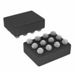 TS5USBC400YFPR
The activity of extra discounts on wholesale prices is in full swing…
Please fill in your contact information and we will send you the latest wholesale price list.





