 ChipApex | Global Electronic Components Supplier
SEARCH
Search Product
Search Post
— IC芯片 | 连接器 | 传感器 | 被动器件 —
Search productSearch post
— IC芯片 | 连接器 | 传感器 | 被动器件 —
Consult the customer manager about the wholesale price.
consultation hotline:86-132-6715-2157
email:[email protected]
Contact the product manager for consultation. One-stop consultation is available.
Do you want a lower wholesale price? Please send us your inquiry and we will reply immediately.
The UCC5630AMWPTR is a multimode SCSI terminator from Texas Instruments, designed for SPI-2, SPI-3, and SPI-4 bus architectures. It automatically senses the bus via the DIFFB pin to switch between single-ended (SE) and low voltage differential (LVD) termination modes. The device operates within a supply voltage range of 2.7V to 5.25V and functions in an ambient temperature range of 0°C to 70°C. In LVD mode, the typical supply current is 20mA with no load, while SE mode draws 10mA. The package is a 36-pin SSOP.
Verify the component status as ACTIVE before procurement. Confirm that the specific ordering suffix matches the required RoHS compliance level and moisture sensitivity classification. Ensure the package type aligns with the design constraints. Check for any recent process change notifications or lifecycle updates directly from the manufacturer.
Select this component when designing systems requiring automatic transition between SE and LVD SCSI modes without external logic. Ensure the PCB layout accommodates the 36-pin SSOP package and connects all HS/GND pins to the ground plane for effective thermal dissipation. Verify that the system power supply remains stable within the 2.7V to 5.25V operating range.
This part belongs to the UCC5630A family of multimode SCSI terminators. It is functionally identical to the UCC5630AFQP but utilizes a 36-pin SSOP package instead of a 48-pin LQFP. Both variants provide the same auto-detection capabilities and electrical characteristics for SCSI bus termination applications.
The UCC5630AFQP serves as a direct functional replacement if a different package is acceptable. Verify that the pinout compatibility and thermal requirements are met when substituting packages. No other direct substitutes are documented in the official datasheet.
It monitors the DIFSENS line voltage. If the voltage is below 0.5V, it selects SE mode. Between 0.7V and 1.9V, it selects LVD mode. Above 2.4V, it enters a high impedance state due to HVD detection.
The MSTR/SLV pin controls the DIFSENS driver. Connecting it to TRMPWR enables the driver (Master), while connecting it to ground disables it (Slave). Only one terminator per bus end should have the driver enabled.
All HS/GND pins must be connected to large area PC board traces or feed-throughs connecting to the ground plane layer to maximize power dissipation capability and reduce junction temperature.
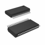 UCC5630AMWPTR
The activity of extra discounts on wholesale prices is in full swing…
Please fill in your contact information and we will send you the latest wholesale price list.





