ChipApex | Global Electronic Components Supplier
SEARCH
Search Product
Search Post
— IC芯片 | 连接器 | 传感器 | 被动器件 —
Search productSearch post
— IC芯片 | 连接器 | 传感器 | 被动器件 —
Consult the customer manager about the wholesale price.
consultation hotline:86-132-6715-2157
email:[email protected]
Contact the product manager for consultation. One-stop consultation is available.
Do you want a lower wholesale price? Please send us your inquiry and we will reply immediately.
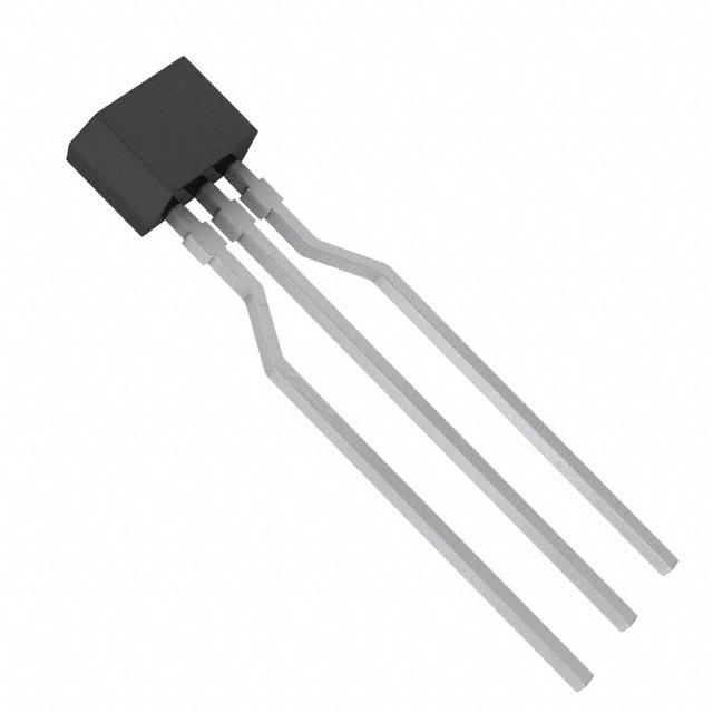
The Panasonic UNR411100A is a small signal PNP silicon epitaxial planar transistor featuring built-in bias resistors, designed for digital circuits. It utilizes the NS-B1 through-hole package with three pins: emitter, collector, and base. The device supports a maximum collector current of 100 mA and a collector-emitter voltage of -50 V. Internal resistance values are R1 = 10 kΩ and R2 = 10 kΩ. Key electrical characteristics include a forward current transfer ratio (hFE) of 35 at IC = -5 mA and VCE = -10 V, a transition frequency of 80 MHz, and a total power dissipation rating of 300 mW.
Verify the exact part number suffix against official Panasonic documentation, as standard distributors may list variations like UNR411E or UNR4111. Confirm lifecycle status directly with the manufacturer, as this series has been subject to maintenance or discontinuation phases. Ensure compliance with RoHS directives if required by your specific application standards.
Select based on the required internal resistor ratios; the UNR4111 variant specifically provides a 1:1 ratio (10k/10k). Verify that the -50V collector-emitter voltage and 100mA current limits meet the circuit requirements. Consider the NS-B1 package dimensions for PCB layout compatibility and ensure thermal management supports the 300mW power dissipation limit.
This component belongs to the UNR411x Series of pre-biased transistors manufactured by Panasonic Electronic Components. The series offers various resistor combinations tailored for different digital switching needs. The UNR411100A represents a specific configuration within this family, distinguished by its 10kΩ/10kΩ internal resistor setup and PNP polarity.
Consult Panasonic's official cross-reference guides for direct replacements. Generic equivalents must match the PNP type, -50V rating, 100mA current, and NS-B1 package. Verify internal resistor values (10kΩ/10kΩ) and hFE characteristics to ensure functional parity in the target circuit.
The UNR4111 features two built-in resistors: R1 is 10 kΩ and R2 is 10 kΩ.
The transition frequency is specified as 80 MHz under conditions of VCB = -10 V, IE = 1 mA, and f = 200 MHz.
Yes, the junction temperature rating is up to 150°C, and the storage temperature range extends from -55°C to +150°C.
 UNR411100A
The activity of extra discounts on wholesale prices is in full swing…
Please fill in your contact information and we will send you the latest wholesale price list.