ChipApex | Global Electronic Components Supplier
SEARCH
Search Product
Search Post
— IC芯片 | 连接器 | 传感器 | 被动器件 —
Search productSearch post
— IC芯片 | 连接器 | 传感器 | 被动器件 —
Consult the customer manager about the wholesale price.
consultation hotline:86-132-6715-2157
email:[email protected]
Contact the product manager for consultation. One-stop consultation is available.
Do you want a lower wholesale price? Please send us your inquiry and we will reply immediately.
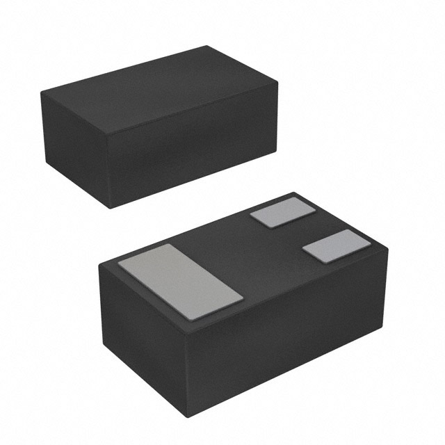
The Panasonic UNRF1A4 is a silicon PNP epitaxial planar transistor with built-in resistors, designed for digital circuits. It utilizes an ML3-N2 ultraminiature leadless package measuring 0.6 mm by 1.0 mm with a height of 0.39 mm. The device features a collector-base voltage (V_CBO) and collector-emitter voltage (V_CEO) rating of -50 V. It supports a maximum collector current of -80 mA and total power dissipation of 100 mW at 25°C. Key electrical characteristics include a forward current transfer ratio (h_FE) of 80 at -5 mA, a transition frequency (f_T) of 80 MHz, and an input resistance (R1) of 10 kΩ.
Verify the current lifecycle status directly with Panasonic before procurement, as this component may be subject to maintenance or discontinuation plans. Confirm that the specific package dimensions and pinout align with your PCB footprint requirements. Ensure compliance with RoHS directives if applicable to your manufacturing standards.
Select this component when space constraints require an ultraminiature footprint with integrated biasing resistors. Verify that the -50 V voltage ratings and -80 mA current limits meet the operational requirements of the target digital circuit. Consider the thermal management capabilities given the 100 mW power dissipation limit in the small leadless package.
This part belongs to Panasonic's lineup of transistors with built-in resistors, specifically engineered for compact digital circuitry. The ML3-N2 package represents a specialized form factor distinct from standard surface-mount packages, prioritizing minimal board area occupation while maintaining necessary electrical isolation and performance for signal processing tasks.
Consult official Panasonic documentation for verified substitute part numbers. Cross-referencing requires matching the PNP configuration, built-in resistor values, ML3-N2 package dimensions, and -50 V voltage ratings to ensure functional compatibility without redesigning the host circuit.
The datasheet specifies an input resistance (R1) of 10 kΩ with a tolerance of ±30%. The resistance ratio R1/R2 is listed as 0.21 typical, but exact individual values for R2 are not explicitly detailed in the provided text.
The junction temperature (Tj) maximum rating is 125°C. The storage temperature range is specified as -55°C to +125°C.
No. The datasheet explicitly states that these products are intended for standard applications such as office equipment and household appliances. Special applications like automobiles require separate consultation due to higher reliability requirements.
 UNRF1A400A
The activity of extra discounts on wholesale prices is in full swing…
Please fill in your contact information and we will send you the latest wholesale price list.