ChipApex | Global Electronic Components Supplier

SEARCH
Search Product
Search Post
— IC芯片 | 连接器 | 传感器 | 被动器件 —
Search productSearch post
— IC芯片 | 连接器 | 传感器 | 被动器件 —
Consult the customer manager about the wholesale price.
consultation hotline:86-132-6715-2157
email:[email protected]
Contact the product manager for consultation. One-stop consultation is available.
Do you want a lower wholesale price? Please send us your inquiry and we will reply immediately.
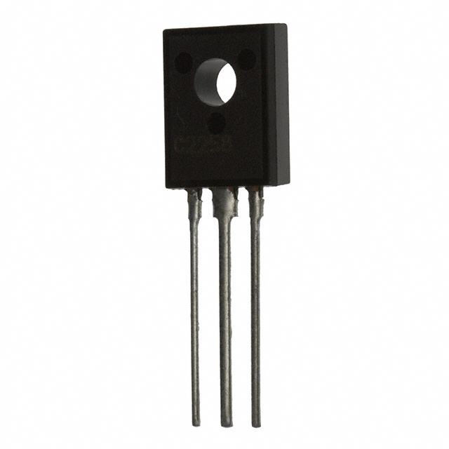
2SC51210P is listed in the Single Bipolar Transistors range at ChipApex. The manufacturer field lists Panasonic Electronic Components. Its product description is TRANS NPN 400V 0.07A TO-126B-A1. Review the specifications below when checking this part for your BOM.
The Panasonic 2SC51210P is a silicon NPN triple diffusion planar transistor designed for general amplification. It features a collector-emitter voltage of 400 V and a collector current rating of 70 mA. The device operates with a transition frequency up to 80 MHz and exhibits low collector output capacitance of 8 pF. Packaged in a TO-126B-A1 format, it supports a junction temperature of 150°C and complies with the RoHS Directive.
Verify the specific lifecycle status before procurement, as this component may be classified under maintenance or discontinued stages. Consult official Panasonic semiconductor channels for the most current Product Standards and availability information prior to final design commitment.
Select this component for applications requiring high voltage isolation and low output capacitance within a compact form factor. Ensure thermal management accommodates the 1.2 W power dissipation limit at ambient temperatures above 25°C. Verify that the required collector current remains within the 70 mA continuous rating.
This part belongs to the 2SC5121 series of silicon NPN transistors manufactured by Panasonic Electronic Components. The 'P' suffix indicates the specific TO-126B-A1 packaging configuration. The device utilizes triple diffusion planar technology to achieve its electrical characteristics suitable for standard electronic equipment.
No public confirmed substitute part numbers are available in the provided documentation. Users should consult Panasonic sales staff for potential alternatives if this component is discontinued.
The maximum collector-emitter voltage (VCEO) is 400 V when the base is open.
No, the TO-126B package is designed to be installed directly onto a heat sink without requiring an additional insulation plate.
The typical forward current transfer ratio (hFE) is 100 when measured at VCE = 10 V and IC = 5 mA.
Explore related parts through Bipolar (BJT), Transistors, Discrete Semiconductor Products, all product categories.
 2SC51210P

The activity of extra discounts on wholesale prices is in full swing…
Please fill in your contact information and we will send you the latest wholesale price list.