ChipApex | Global Electronic Components Supplier

SEARCH
Search Product
Search Post
— IC芯片 | 连接器 | 传感器 | 被动器件 —
Search productSearch post
— IC芯片 | 连接器 | 传感器 | 被动器件 —
Consult the customer manager about the wholesale price.
consultation hotline:86-132-6715-2157
email:[email protected]
Contact the product manager for consultation. One-stop consultation is available.
Do you want a lower wholesale price? Please send us your inquiry and we will reply immediately.
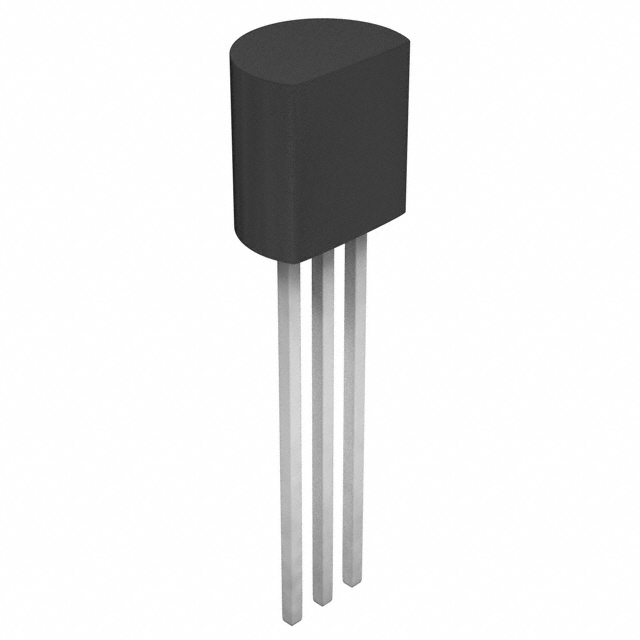
The Toshiba 2SD2695 is a silicon NPN epitaxial planar Darlington power transistor housed in a TO-92MOD package. It features a high DC current gain of 2000 minimum at VCE = 2 V and IC = 1 A, alongside a low collector-emitter saturation voltage of 1.5 V maximum under the same conditions. The device includes an integrated Zener diode between the collector and base terminals for protection. Absolute maximum ratings specify a collector-base voltage of 50 V, a collector-emitter voltage of 60 V, and a continuous collector current of 2 A.
Verify RoHS compatibility status by checking the lot number marking on the component body or contacting the manufacturer directly, as indicated in the datasheet notes. Ensure the ordering suffix matches the required environmental compliance specifications. Confirm the package type is TO-92MOD and verify pinout alignment with the base, emitter, and collector configuration before integration into the design.
Select this component when high current amplification is required within a compact form factor. The built-in Zener diode simplifies circuit design by protecting against voltage spikes across the collector-base junction. Consider the thermal derating requirements for continuous operation near the maximum power dissipation limit of 0.9 W. Evaluate the transition frequency characteristics if high-speed switching performance is critical for the specific application timing.
This part belongs to Toshiba's lineup of silicon NPN epitaxial planar transistors designed for power handling. The Darlington configuration provides superior current gain compared to standard bipolar transistors. The TO-92MOD package offers a robust mechanical structure suitable for through-hole mounting while maintaining electrical isolation capabilities required in various electronic assemblies.
Consult official replacement lists from Toshiba Semiconductor and Storage for verified equivalent components. Cross-referencing with other manufacturers requires careful validation of absolute maximum ratings and electrical parameters to ensure functional compatibility without compromising circuit reliability.
A Zener diode is included internally between the collector and base terminals to provide protection against voltage transients.
The minimum DC current gain (hFE) is specified as 2000 when measured at VCE = 2 V and IC = 1 A.
The collector-emitter breakdown voltage (V(BR)CEO) is rated at 60 V with a test condition of IC = 10 mA and IB = 0.
 2SD2695,T6F(J

The activity of extra discounts on wholesale prices is in full swing…
Please fill in your contact information and we will send you the latest wholesale price list.