ChipApex | Global Electronic Components Supplier
SEARCH
Search Product
Search Post
— IC芯片 | 连接器 | 传感器 | 被动器件 —
Search productSearch post
— IC芯片 | 连接器 | 传感器 | 被动器件 —
Consult the customer manager about the wholesale price.
consultation hotline:86-132-6715-2157
email:[email protected]
Contact the product manager for consultation. One-stop consultation is available.
Do you want a lower wholesale price? Please send us your inquiry and we will reply immediately.
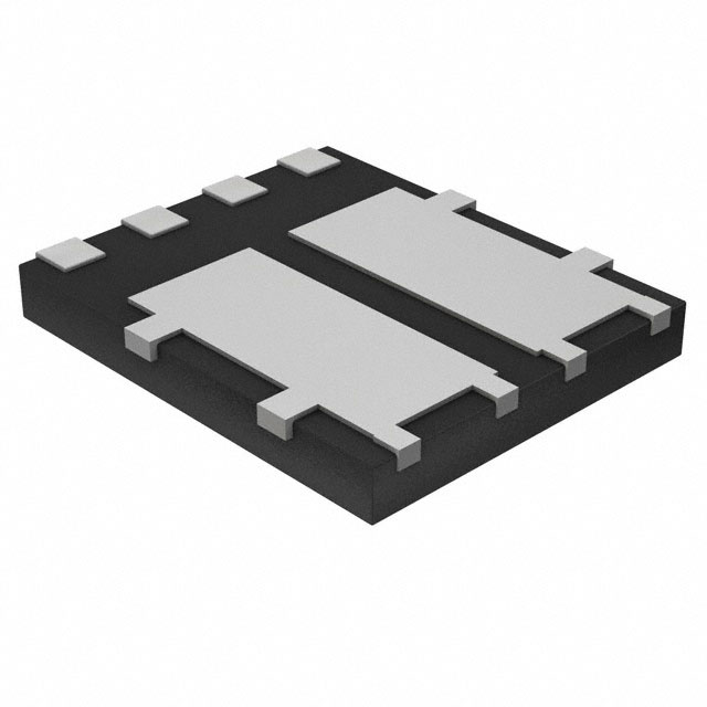
The DMC1016UPD-13 is a complementary pair enhancement mode MOSFET in a PowerDI5060-8 package. It integrates an N-channel Q1 and a P-channel Q2. Q1 offers a drain-source voltage of 12V, with RDS(ON) at 17mΩ (VGS=4.5V) supporting 9.5A continuous current. Q2 provides -20V, with RDS(ON) at 20mΩ (VGS=-4.5V) supporting -8.7A. The device features low input capacitance for fast switching, ESD protection on the P-channel gate, and operates within a junction temperature range of -55°C to +150°C.
Verify the specific ordering suffix '-13' corresponds to the 2500-unit tape and reel packaging configuration. Confirm that the component meets RoHS 3 and halogen-free requirements if mandated by your assembly specifications. Ensure the procurement channel is authorized to guarantee JEDEC qualification standards are maintained.
Select this part when a compact complementary switch solution is required for low-voltage DC-DC or load switch topologies. Verify that the system's gate drive voltage aligns with the specified RDS(ON) conditions (e.g., 4.5V or 2.5V). Consider the thermal resistance values if operating near the maximum junction temperature limits.
This component belongs to Diodes Incorporated's complementary MOSFET family designed for portable electronics. It utilizes the PowerDI5060-8 case style, which provides enhanced thermal performance compared to standard surface-mount packages. The device is engineered to balance low static losses with dynamic switching speed for efficient power delivery.
For automotive applications requiring AEC-Q101 qualification and PPAP capability, consult the related automotive grade parts with the 'Q-suffix'. Verify pinout compatibility and electrical parameters before substituting with other complementary MOSFET pairs from different manufacturers.
The N-channel Q1 supports a continuous drain current of 9.5A at TA = +25°C and 7.6A at TA = +70°C.
Yes, the datasheet specifies that the Q2 P-Channel MOSFET includes ESD protected gate functionality.
The thermal resistance from junction to case (RθJC) is specified as 6.2 °C/W.
 DMC1016UPD-13
The activity of extra discounts on wholesale prices is in full swing…
Please fill in your contact information and we will send you the latest wholesale price list.