ChipApex | Global Electronic Components Supplier
SEARCH
Search Product
Search Post
— IC芯片 | 连接器 | 传感器 | 被动器件 —
Search productSearch post
— IC芯片 | 连接器 | 传感器 | 被动器件 —
Consult the customer manager about the wholesale price.
consultation hotline:86-132-6715-2157
email:[email protected]
Contact the product manager for consultation. One-stop consultation is available.
Do you want a lower wholesale price? Please send us your inquiry and we will reply immediately.
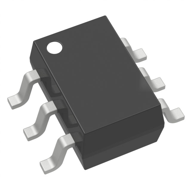
The DMC1028UVT-13 is a complementary pair enhancement mode MOSFET from Diodes Incorporated, integrating an N-channel and a P-channel device within a single TSOT-26 package. The N-channel transistor (Q1) features a drain-source voltage of 12V, with on-resistance values of 25mΩ at VGS=4.5V, 32mΩ at VGS=2.5V, and 40mΩ at VGS=1.8V. Continuous drain currents reach 6.1A at 25°C for the N-channel and -3.5A for the P-channel (Q2). The P-channel device supports a -20V breakdown voltage, exhibiting on-resistances of 80mΩ, 100mΩ, 140mΩ, and 210mΩ at respective gate voltages of -4.5V, -2.5V, -1.8V, and -1.5V. Total power dissipation is rated at 0.8W steady-state.
Verify the specific ordering suffix to confirm packaging quantity. The -13 suffix indicates a tape and reel configuration containing 10,000 units per reel. Confirm that the component meets RoHS compliance standards and is halogen-free if required by your manufacturing specifications. Ensure the TSOT-26 footprint matches your PCB layout requirements before finalizing procurement.
Select this component when space-constrained designs require a matched N-P channel pair for load switches or level shifting. The low on-resistance makes it suitable for applications demanding minimal voltage drop. Verify that the 12V rating for the N-channel and -20V for the P-channel align with your system's operating voltages. Consider the thermal resistance of 157°C/W for ambient temperature calculations.
This part belongs to Diodes Incorporated's advanced generation MOSFET portfolio designed to minimize on-state resistance while maintaining superior switching performance. It serves as a complementary pair solution, replacing discrete components to save board space. The product is manufactured using silicon technology and is intended for general-purpose power management applications where efficiency and size are critical factors.
Direct replacements must match the TSOT-26 package and complementary N-P channel configuration. Verify that substitute parts offer comparable on-resistance and voltage ratings. Check for equivalent pinout assignments to ensure compatibility without circuit redesign.
 DMC1028UVT-13
The activity of extra discounts on wholesale prices is in full swing…
Please fill in your contact information and we will send you the latest wholesale price list.